Method for detecting movement of image sensors

a technology of image sensor and movement, applied in the field of detection of can solve the problems of slow determination rate and many sources of noise, and achieve the effect of ensuring the accuracy of comparison, reducing data and operation, and quickly and accurately determining the movement of image sensor

Active Publication Date: 2006-12-19
SAMSUNG ELECTRONICS CO LTD
View PDF22 Cites 13 Cited by
  • Summary
  • Abstract
  • Description
  • Claims
  • Application Information

AI Technical Summary

Benefits of technology

[0009]The object of the present invention is to provide a method to detect the movement of an image sensor. When comparing the original image and the following image, the present invention doesn't compare all the frame blocks in the original image with the following image. Rather, it selects a single frame block in the original image to fully search the following image. In addition, the present invention provides three verification methods to ensure the accuracy of the comparison. The three verification methods are cross checking, maximum error threshold, and determining the matched frame block number of the result of the comparison. The present invention quickly and accurately determines the movement of an image sensor using less data and operation.

Problems solved by technology

However, there are actually many sources of noise, not only from image and process variation, but also from the environment of the image sensor such as temperature and illumination variation.
Therefore, the conventional method requires using a large amount of data, so the determining rate is slow.

Method used


Image

  • Method for detecting movement of image sensors
  • Method for detecting movement of image sensors
  • Method for detecting movement of image sensors

Examples


first embodiment

[0014

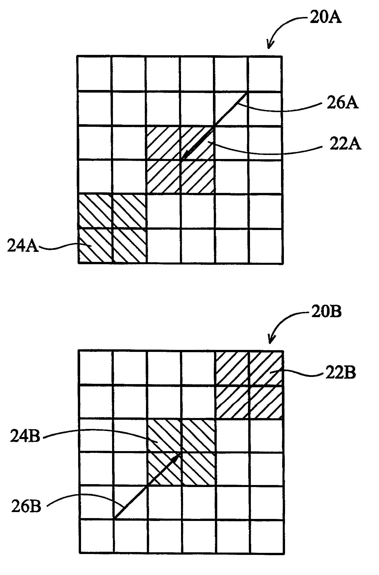
[0015]FIG. 2A and FIG. 2B show the method to determine the movement of an image sensor by block matching according to the embodiment of the present invention.

[0016]The first frame 20A is the image captured by the image sensor in a first location, and the second frame 20B is the image captured by the image sensor when the image sensor moves to a second location. Here, the size of the frame captured by the image sensor is 6×6 units. The frame block 22A is captured from the first frame 20A, wherein the size of the frame block 22A is 2×2 units. Then, frame block matching is performed to find the frame block 22B matching the frame block 22A in the second frame 20B, wherein the value of the matching function is the minimum. In addition, the frame block 22A is near the center of the first image 20A to avoid missing the matched frame block in the second image because the image sensor has moved too far.

[0017]Next, a verification process is performed, the present embodiment performing cr...

second embodiment

[0019

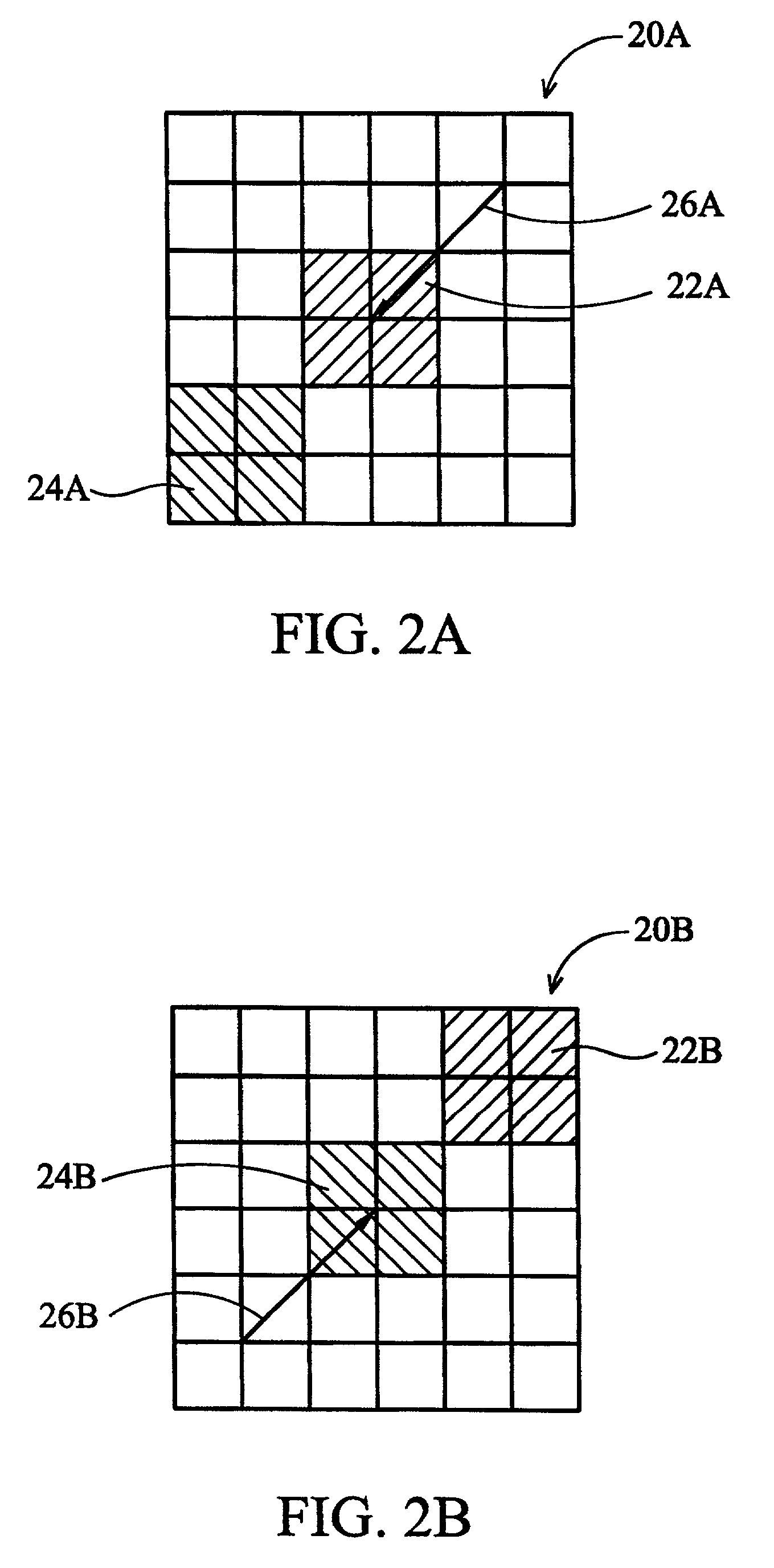
[0020]FIG. 2A and FIG. 2B show the method to determine the movement of an image sensor by block matching according to the embodiment of the present invention.

[0021]The first frame 20A is the image captured by the image sensor in a first location, and the second frame 20B is the image captured by the image sensor when the image sensor moves to a second location. Here, the size of the frame captured by the image sensor is 6×6 units. The frame block 22A is captured from the first frame 20A, wherein the size of the frame block 22A is 2×2 units. Then, frame block matching is performed to find the frame block 22B matching the frame block 22A in the second frame 20B, wherein the value of the matching function is the minimum. In addition, the frame block 22A is near the center of the first image 20A to avoid missing the matched frame block in the second image because the image sensor has moved too far.

[0022]Next, a verification process is performed, the present embodiment performing th...

third embodiment

[0025

[0026]FIG. 2A and FIG. 2B show the method to determine the movement of an image sensor by block matching according to the embodiment of the present invention.

[0027]The first frame 20A is the image captured by the image sensor in a first location, and the second frame 20B is the image captured by the image sensor when the image sensor moves to a second location. Here, the size of the frame captured by the image sensor is 6×6 units. The frame block 22A is captured from the first frame 20A, wherein the size of the frame block 22A is 2×2 units. Then, frame block matching is performed to find the frame block 22B matching the frame block 22A in the second frame 20B, wherein the value of the matching function is the minimum. In addition, the frame block 22A is near the center of the first image 20A to avoid missing the matched frame block in the second image because the image sensor has moved too far.

[0028]Next, a verification process is performed, the present embodiment ascertaining ...


PUM


Abstract

A method to detect the movement of an image sensor according to captured images. An image region is captured from a first image. Then, a first corresponding region matching the first region is captured from a second image. A second image region is captured from the second image. Then, a second corresponding region matching the second captured image region is captured from the first image. Finally, the movement of the image sensor is determined according to the first region and the first corresponding region when a first relative distance between the first region and the first corresponding region is the same as a second relative distance of the second captured image region and the second corresponding region, but in the opposite direction.

Description

[0001]This application claims priority from Taiwanese application no. 90122445, filed in Taiwan, R.O.C., on Sep. 11, 2001, pursuant to 35 U.S.C. 119(a)–(d).BACKGROUND OF THE INVENTION[0002]1. Field of the Invention[0003]The present invention relates in general to a method to detect the movement of an image sensor. In particular, the present invention relates to a method for detecting movement of an image sensor which, by comparing the images captured by the image sensor at different locations, finding the matched images and performing some verification processes, the movement of the image sensor is determined.[0004]2. Description of the Related Art[0005]Normally, the prior arts use block matching to determine the movement of an image sensor. Ideally, using this method can correctly find a matched frame block generated from the matching function, mean squared error (MSE) or mean absolute difference (MAD), then use the matched frame blocks to calculate the movement of the image sensor...

Claims


Application Information

Patent Timeline
Patent Type & Authority Patents(United States)
IPC IPC(8): H04N5/228G06K9/56G06K9/64G09G5/08H04N5/14H04N5/222
CPCH04N5/145
Inventor LIN, CHUN-HUANGLAN, JENG-FENGHUANG, CHIEN-CHANG
Owner SAMSUNG ELECTRONICS CO LTD
Why Eureka
Try Eureka