Modular, scalable thermal solution

a thermal solution and modular technology, applied in the field of modular, scalable thermal solutions for computer hardware, can solve the problems of cooling system replacement, processor to generate more heat, and more powerful processors may generate more heat than the original processors

Active Publication Date: 2006-12-19
NVIDIA CORP
View PDF10 Cites 25 Cited by
  • Summary
  • Abstract
  • Description
  • Claims
  • Application Information

AI Technical Summary

Benefits of technology

[0010]One advantage of the disclosed cooling system is that, among other things, the cooling system can be selectively upgraded through the addition of supplemental cooling modules rather than replaced in its entirety when additional cooling capacity is required.

Problems solved by technology

The increase in average processing level may cause the processor to generate more heat.
Also, in the case where a processor is upgraded, the new, more powerful processor may generate more heat than the original processor.
In such situations, if the existing cooling system does not have the capacity to counter the increased levels of generated heat, then the cooling system may have to be replaced.
Replacing an entire cooling system is both time consuming and costly.

Method used


Image

  • Modular, scalable thermal solution
  • Modular, scalable thermal solution
  • Modular, scalable thermal solution

Examples


second embodiment

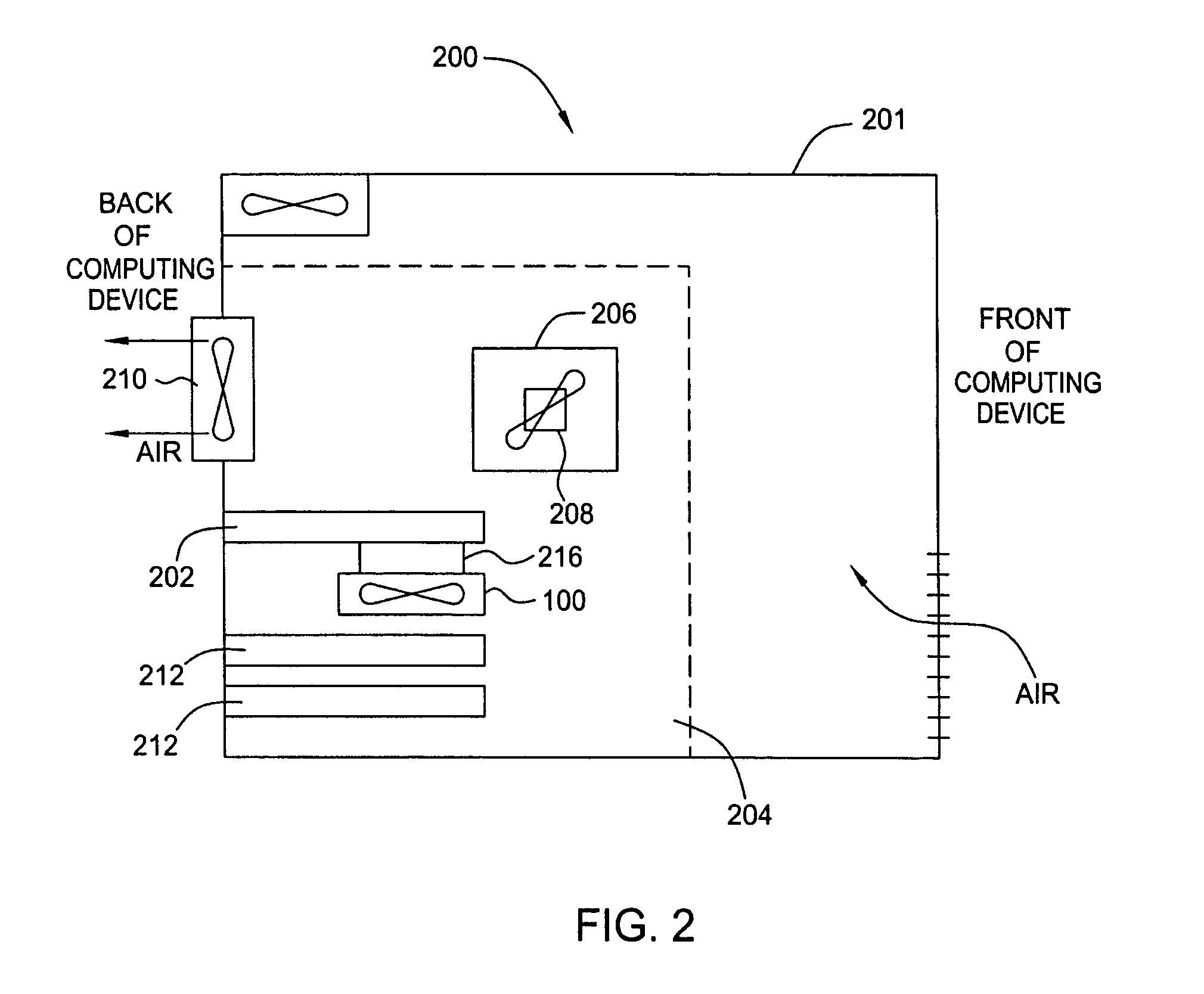
[0044]FIG. 8 is schematic diagram illustrating a computing system 801 adapted for use with a modular, scalable cooling system 800, according to the present invention. Although implementations of cooling system 800 are described within the exemplary context of computing system 801, those skilled in the art will appreciate that cooling system 800 may be adapted to cool any type of heat-generating electronic device that requires heat dissipation.

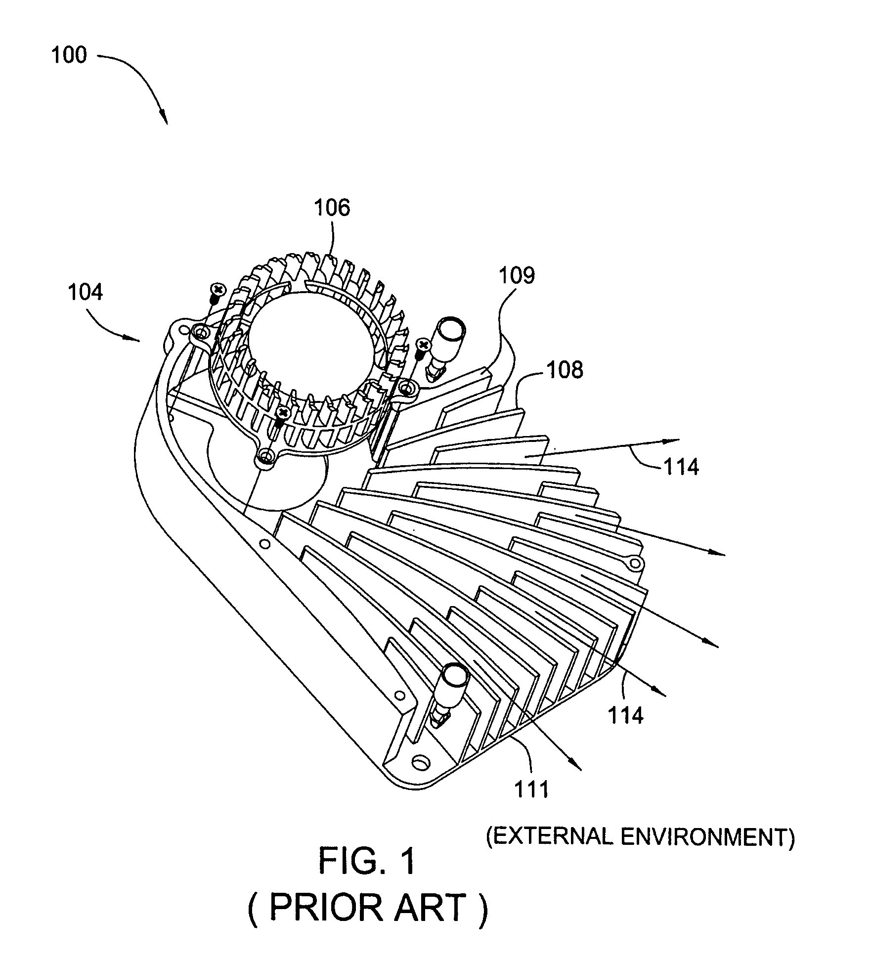
[0045]In the embodiment illustrated, cooling system 800 is configured for coupling to a GPU 804 in lieu of a conventional cooling system, such as cooling system 100 of FIG. 1. Cooling system 800 may include, without limitation, a core cooling module 802, a supplemental cooling module 850, a first interface 806 and a second interface 870. As described above, core cooling module 802 may operate independently or in combination with one or more supplemental cooling modules to dissipate heat from GPU 804.

[0046]As shown, core cooling module 802 is th...

third embodiment

[0051]FIG. 9A is schematic diagram illustrating computing system 905 adapted for use with a modular, scalable cooling system 900A, according to the present invention. Specifically, cooling system 900A is adapted for simultaneously cooling two or more heat-generating electronic devices (e.g., graphics processors 901 and 903) implemented within computing system 905.

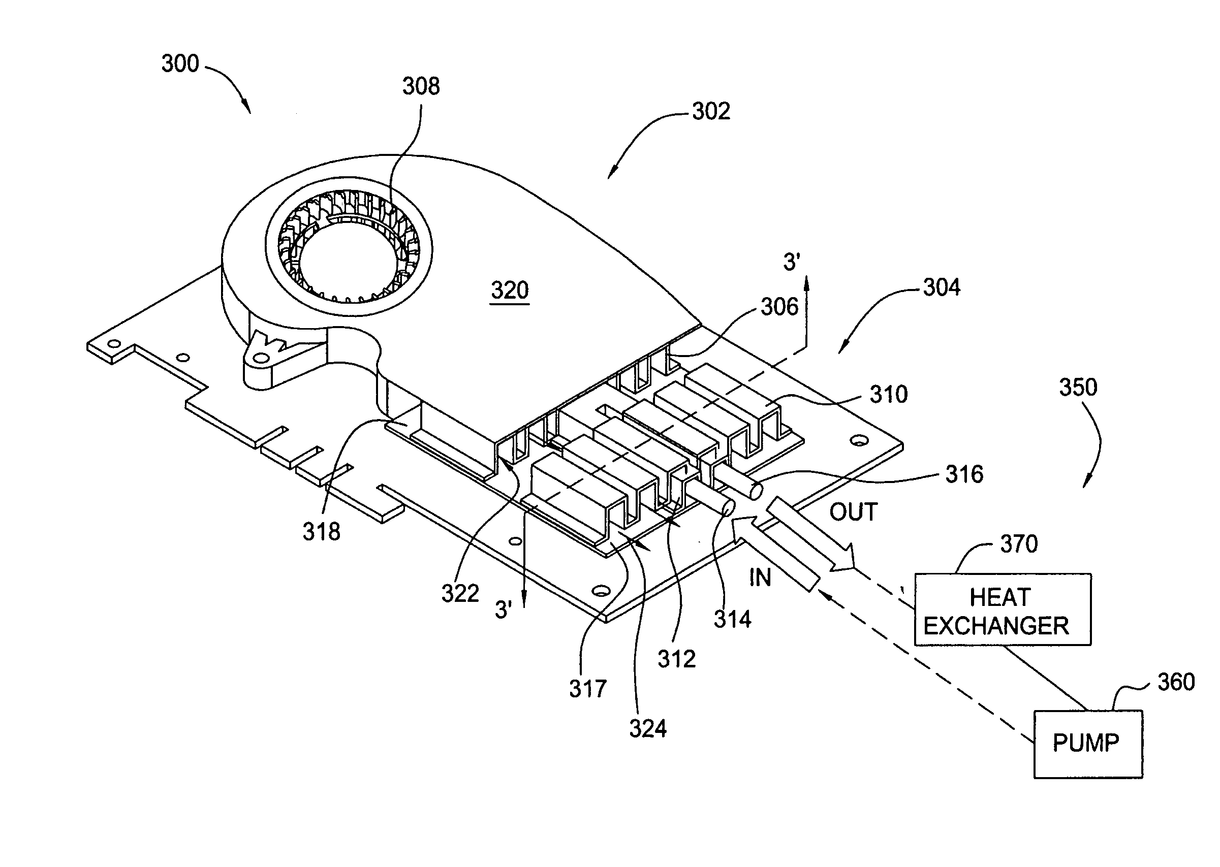
[0052]In one embodiment, cooling system 900A includes two or more core cooling modules 9021 and 9022 (hereinafter collectively referred to as “core cooling modules 902”), where one of core cooling modules 902 isothermally coupled to one of the heat-generating electronic devices. In addition, cooling system 900A includes, without limitation, an internal supplemental cooling module 950A, configured in a manner substantially similar to supplemental cooling module 350 of FIG. 3, and two or more first interfaces 9081 and 9082 (hereinafter collectively referred to as “first interfaces 908”), where one of first interfaces 908 is a...


PUM


Abstract

One embodiment of a modular, scalable cooling system includes a core cooling module configured to be thermally coupled to a heat-generating electronic device and a supplemental cooling module configured to be thermally coupled to the core cooling module. A first interface attached to the core cooling module is configured to thermally couple the core cooling module to the supplemental cooling module. The core cooling module and the supplemental cooling module may be used alone or in combination to dissipate heat from the heat-generating electronic device.

Description

CROSS-REFERENCE TO RELATED APPLICATIONS[0001]This application is a continuation-in-part of co-pending U.S. patent application Ser. No. 10 / 822,958, filed Apr. 12, 2004, which is herein incorporated by reference.BACKGROUND OF THE INVENTION[0002]1. Field of the Invention[0003]This invention relates generally to computer hardware and more particularly to a modular, scalable thermal solution for computer hardware.[0004]2. Description of the Related Art[0005]FIG. 1 is an isometric view illustrating a prior art cooling system 100 used, for example, to cool electronic devices (e.g., a processor). As shown, cooling system 100 characteristically includes a heat sink assembly 104, which further includes a fan 106, walls 109 and a bottom plate 111. Typically, cooling system 100 is thermally coupled to an electronic device, for example using thermal adhesive having thermal properties that facilitate transferring heat generated by the electronic device to bottom plate 111 of heat sink assembly 10...

Claims


Application Information

Patent Timeline
Patent Type & Authority Patents(United States)
IPC IPC(8): H05K7/20G06F1/20
CPCG06F1/20G06F1/206G06F2200/201
Inventor WALTERS, JOSEPH DOUGLASSSTEFANOSKI, ZORANLEE, TOMMY C.
Owner NVIDIA CORP
Why Eureka
Try Eureka