Plate heat exchanger

a heat exchanger and plate technology, applied in the field of plate heat exchangers, can solve the problem of difficult manufacturing of such a separate sensor

Inactive Publication Date: 2006-12-26
CETETHERM AB
View PDF10 Cites 25 Cited by
  • Summary
  • Abstract
  • Description
  • Claims
  • Application Information

AI Technical Summary

Benefits of technology

[0006]The object of the present invention is to overcome the problems mentioned above and to provide a plate heat exchanger with an improved sensor device, which can be manufactured in an easy manner.
[0007]This object is achieved by the plate heat exchanger initially defined, which is characterised in that the closed space at least partly is defined by at least one of said plates. In such a way, the closed space may be provided in very close, heat-transferring contact with one of said fluids. In such a way, the possibilities are created for obtaining a large contact surface of the sensor device. By such a large contact surface a significant driving force is obtained for said sensing means, for instance a control valve, the valve position of which is controlled by means of said medium. Moreover, by the sensor device according to the invention a small time constant and a short dead time are obtained, i.e. a very quick reaction to changes of the temperature of any of the fluids is thus obtained. Consequently, the sensor device according to the invention is not to any part provided in the porthole channels of the plate heat exchanger and will not form any flow obstruction. Advantageously, the closed space is at least partly defined by at least two of said plates. According to the invention, the closed space does not require any additional casing or the like, but it may be defined merely by a number of the plates included in the plate package. In applications where the temperature of the second fluid is to be controlled at the same time as the flow of the second fluid approaches zero, which is a typical situation in a tap water application, it is an advantage that the sensor device according to the invention is positioned within the plate heat exchanger and thus is quickly influenced by temperature changes. Then the sensor device transmits quickly a signal to a control valve, for instance, that it is to be closed, wherein the flow of the first fluid quickly will be stopped. This means that as little energy as possible will be stored in the heat exchanger, and thus raised temperatures resulting in risks of scalding and lime deposits are avoided. At the same time the return temperature of the first fluid is kept down and the flow quantity passing through the first passages will be the smallest possible.
[0008]According to a further embodiment of the invention, the closed space is positioned in such a way that it is in heat-transferring contact with one of said first fluid and said second fluid. The closed space may also be positioned in such a way that it is in heat-transferring contact with said first fluid and said second fluid. Such an application, where the sensor device senses both fluids, is advantageous in automative control systems, i.e. such systems that are driven by means of energy from the process to be controlled. Such systems have a property, which always result in a certain control deviation, which in for instance electrical control systems can be removed by means of an integrating function. In a tap water application, where the sensor device according to conventional technique senses the temperature on the secondary side, i.e. of the second fluid, the negative influence of the control deviation increases if the load increases. If the temperature on the primary side, i.e. in the first fluid, is too high, the control deviation will be positive. By letting the sensor device sensing both the first fluid and the second fluid, one may compensate for the control deviation contributed to by the primary temperature.

Problems solved by technology

The provision of such a separate sensor is difficult from a manufacturing point of view.
The known arrangements also have the disadvantage that the time constant is long, i.e. it takes a relatively long time before a temperature change of one or both fluids results in a sufficient influence on said medium and thus in a desired change of a valve position, for instance.

Method used


Image

  • Plate heat exchanger
  • Plate heat exchanger
  • Plate heat exchanger

Examples


first embodiment

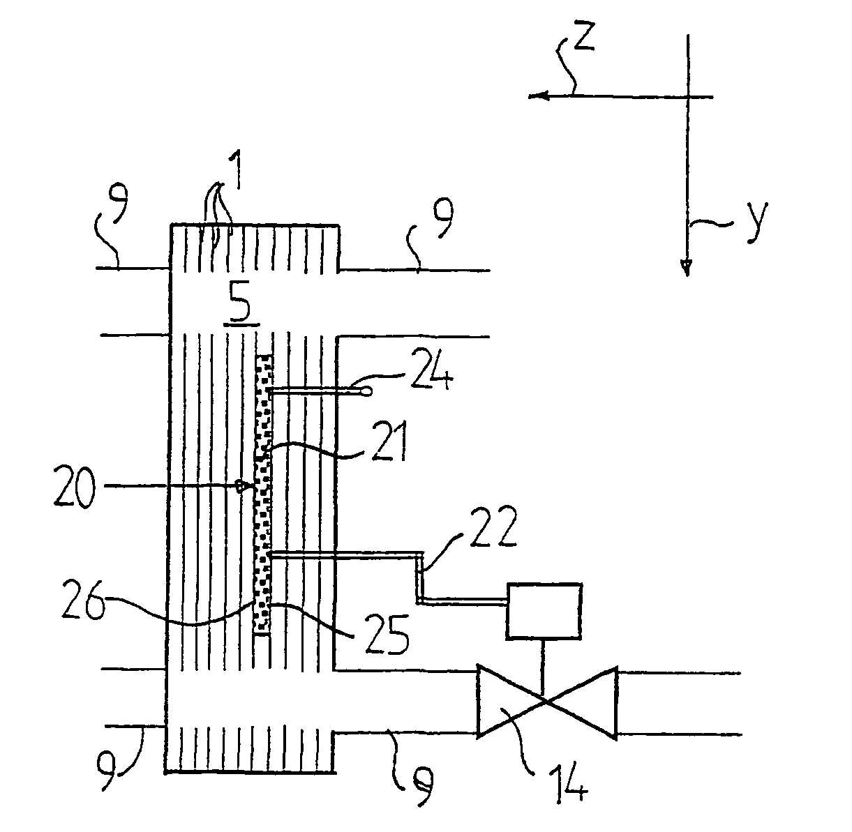
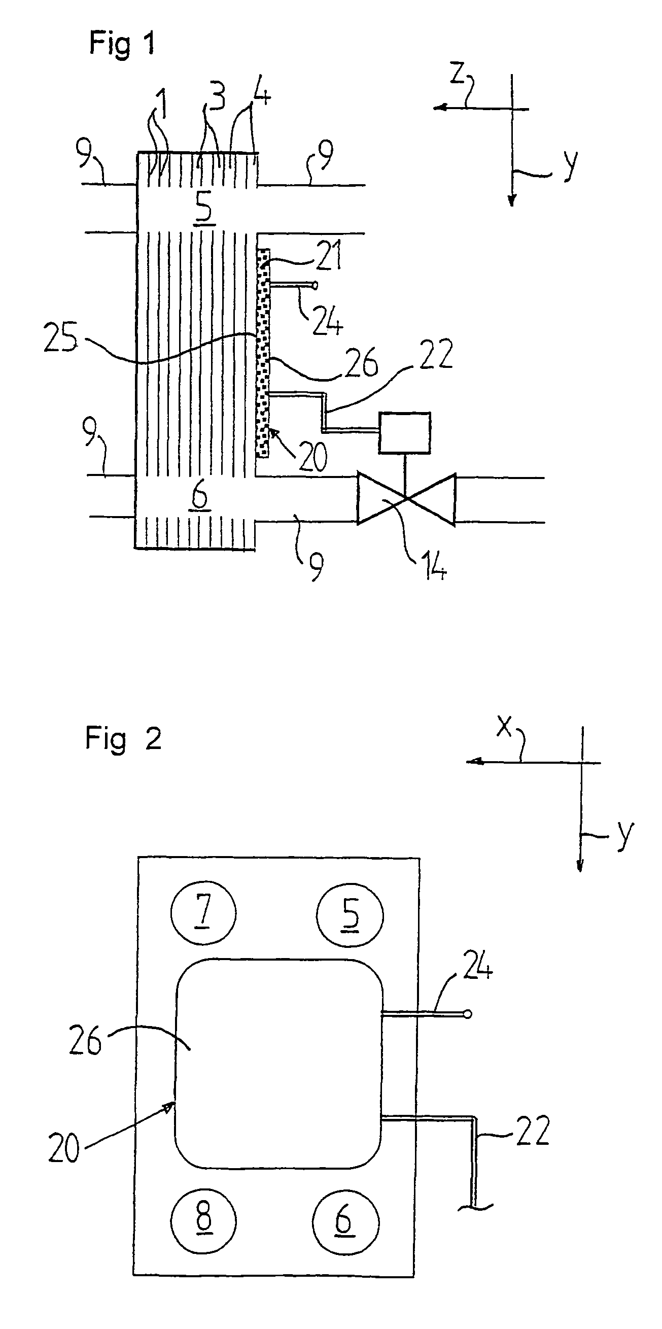
[0026]FIGS. 1 and 2 disclose a plate heat exchanger according to the invention. The plate heat exchanger includes a number of heat transfer plates 1, which form a plate package. The heat transfer plates 1 are pressed to such a shape that, when they are arranged beside each other to said plate package, a plate interspace is formed between each pair of plates 1. The plate interspaces are arranged to form first passages 3 for a first fluid and second passages 4 for a second fluid. The first passages 3 are separated from the second passages 4.

[0027]Furthermore, the plate heat exchanger includes four porthole channels 5, 6, 7, 8, which extend through all plates 1, wherein two of the porthole channels communicate with the first passages 3 and two of the porthole channels communicate with the second passages 4. It is to be noted that the plate heat exchanger according to the invention also may be of a type, which has 2 or 6 porthole channels. Each porthole channel 5–8 is formed by an openi...

fourth embodiment

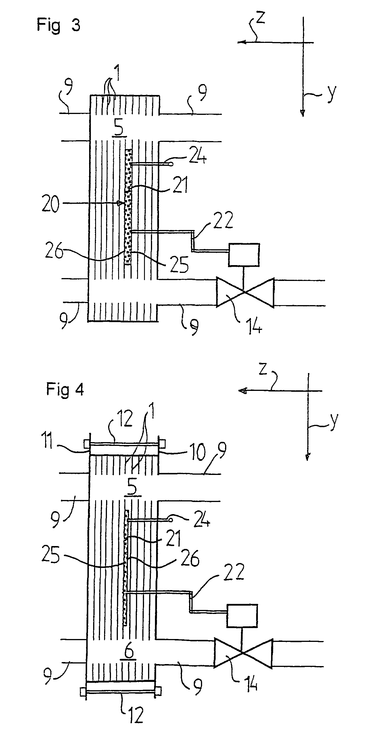
[0040]FIGS. 5–7 disclose the invention where the closed space 21 extends in the direction z, i.e. transversally through the heat transfer plates 1. In the embodiment disclosed in FIG. 5, the space 21 extends through all heat transfer plates 1 except for the end plates 10, 11. The closed space 21 is in this embodiment substantially completely defined merely by plates 1. Each plate 1 includes a hole, which is defined by an edge portion 30 extending around the hole. The edge portion 30 may be bent from the extension plane of the plate 1 and form a collar or flange 31 extending around the hole. The edge portions 30 and the flanges 31 are formed in such a way that they abut sealingly another plate 1. The edge portions 30 may thus be produced in connection with the manufacturing of the plate 1 by means of a pressing operation. The edge portion 30 and the flange 31 then form the edge on a depression and the hole may be made in the depression during the pressing operation proper or in a sub...


PUM


Abstract

The invention refers to a plate heat exchanger, which includes a sensor device and a plate package of heat transfer plates (1). The heat transfer plates form between the plates (1) first passages (3) for a first fluid and second passages (4) for a second fluid. The sensor device includes a space (21), which is closed to the first passages (3) and the second passages (4). The closed space (21) is arranged to contain a medium, which can be influenced by the temperature of at least one of the fluids, and to be connectable to a device (14) for sensing a pressure change of the medium in the closed space (21). The closed space (21) is at least partly defined by at least one of the plates (1).

Description

BACKGROUND OF THE INVENTION AND PRIOR ART[0001]The present invention refers to a plate heat exchanger, which includes a sensor device and a plate package of heat transfer plates, which are provided to form, between the plates, first passages for a first fluid and second passages for a second fluid, wherein the sensor device includes a space, which is closed to the first passages and the second passages, wherein the closed space is arranged to contain a medium, which is provided to be influenced by the temperature of at least one of said fluids, and to be connectable to means for sensing a pressure change of said medium in the closed space.[0002]EP-B-608 195 discloses such a plate heat exchanger with a sensor device, which includes a temperature sensor with an elongated shape. The temperature sensor extends in one of the porthole channels of the plate heat exchanger, which communicates with some of the heat transfer passages of the plate package. The temperature sensor communicates v...

Claims


Application Information

Patent Timeline
Patent Type & Authority Patents(United States)
IPC IPC(8): B60H1/00F28D9/00F28D9/02F28F27/02
CPCF28D9/005F28F27/02F28F2250/06
Inventor HELIN, PER-OLA MAGNUSNILSSON, MAGNUS BRORSTENHEDE, CLAES
Owner CETETHERM AB
Why Eureka
Try Eureka