Trigger selector for a nail gun

a selector and nail gun technology, applied in the field of nail guns, can solve the problems of complex structure of selector switches, manual operation of nail guns, and inconvenient operation of nail guns, and achieve the effect of simple structur

Inactive Publication Date: 2006-12-26
REXON IND CORP LTD
View PDF8 Cites 33 Cited by
  • Summary
  • Abstract
  • Description
  • Claims
  • Application Information

AI Technical Summary

Benefits of technology

[0013]The main objective of the invention is to provide a trigger selector for a nail gun that has a simple structure and enables a single shot or semiautomatic mode of the nail gun.

Problems solved by technology

However, each shooting of the nail gun requires both manual operations of pressing the safety and squeezing the trigger.
Therefore, the operation of the nail gun can be very inconvenient when many nails must be driven into an object.
However, the selector switch has an intricate structure, and the nail gun must be modified substantially to accommodate to the selector switch.
Therefore, the nail gun is hard to assemble.

Method used


Image

  • Trigger selector for a nail gun
  • Trigger selector for a nail gun
  • Trigger selector for a nail gun

Examples


Embodiment Construction

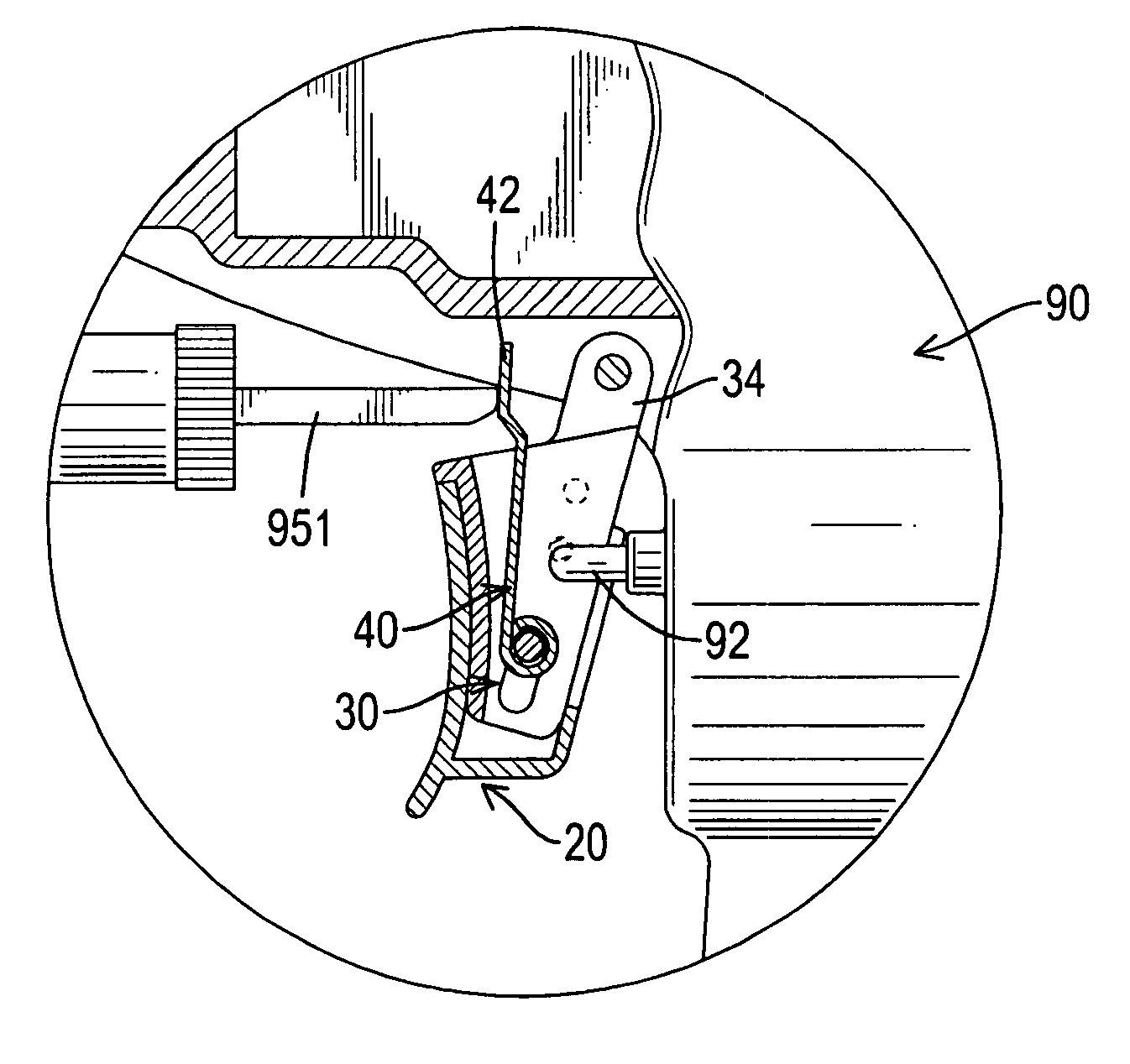
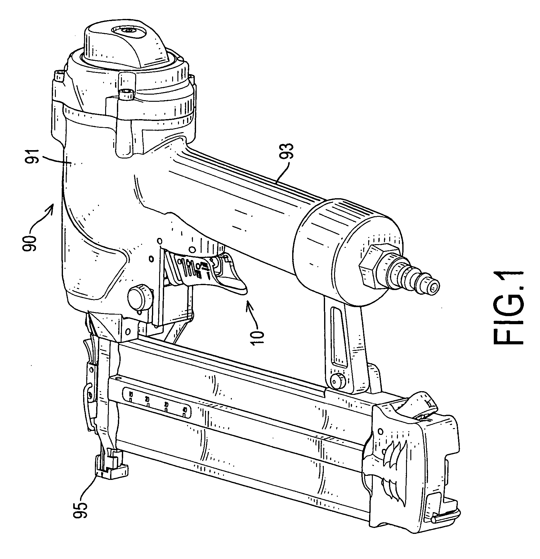
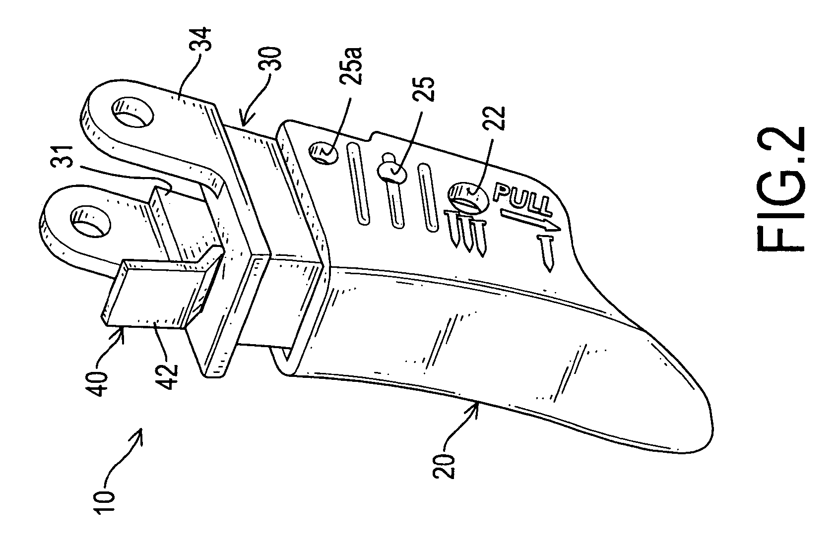
[0029]With reference to FIGS. 1 and 4, a trigger selector (10) in accordance with the present invention is used with a nail gun (90) and comprises a trigger (30), a selector sleeve (20), an enabling lever (40) and a pin (50). The nail gun (90) has a casing (91), a safety (95), a handgrip (93), an air passage (not shown) and a valve (92). The casing (91) has a front end, a rear end and a bottom. The handgrip (93) is formed on and extends perpendicularly down from the casing (91) and has a front end. The air passage is defined through the handgrip (93) and the casing (91). The valve (92) is mounted in front of the handgrip (93) and selectively admits compressed air into the air passage when the valve (92) is pushed. The safety (95) is slidably mounted on the front end of the casing (91) and has a front foot and an activation rod (951) having a rear end.

[0030]The trigger selector (10) is mounted on the bottom of the casing (91) in front of the handgrip (93) between the rear end of the ...


PUM

PropertyMeasurementUnit
structureaaaaaaaaaa
shapeaaaaaaaaaa
sizeaaaaaaaaaa

Abstract

A trigger selector is used with a nail gun. The nail gun has a body and a safety. The body has a casing, a handgrip, an air passage and a valve. The trigger selector has a trigger, a selector sleeve, an enabling lever and a pin. The trigger has a recess and two slots. The selector sleeve is mounted slidably on the trigger and has two mounting holes corresponding to the slots in the trigger. The enabling lever is mounted pivotally in the recess, extends from the open top of the trigger, selectively aligns with the safety and aligns with the valve. The nail gun is adjusted a single shot or a semiautomatic mode by sliding the selector sleeve relative to the trigger.

Description

BACKGROUND OF THE INVENTION[0001]1. Field of the Invention[0002]The present invention relates to a nail gun, and more particularly to a trigger selector for a nail gun that has a simple structure and adjusts single or continuous shooting of the nail gun.[0003]2. Description of Related Art[0004]A conventional nail gun comprises a body, a safety, a trigger and a magazine.[0005]The body has a casing, a handgrip, an air passage and a valve. The casing has a front end, a rear end and a bottom. The handgrip is formed on and extends perpendicularly down from the bottom of the casing and has a front and a bottom end. The air passage is defined through the body. The valve is mounted in front of the handgrip and selectively admits compressed air into the air passage.[0006]The safety is slidably mounted on the front end of the casing and has a front foot and an activation rod having a rear end.[0007]The trigger is mounted on the bottom of the casing in front of the handgrip between the rear en...

Claims


Application Information

Patent Timeline
Patent Type & Authority Patents(United States)
IPC IPC(8): B25C1/04
CPCB25C1/043
Inventor KE, CHIH-CHINE
Owner REXON IND CORP LTD
Why Eureka
Try Eureka