System and method for controlling the movements of container handling device

a container and handling device technology, applied in the direction of load-engaging elements, transportation and packaging, etc., can solve the problems of spreader service at more frequent intervals, spreader sliding surface telescopic parts that require a lot of power to overcome friction, and spreader to be serviced. a lot more often, the control system of the invention is convenient to use, and the effect of reducing rolling resistan

Inactive Publication Date: 2006-12-26
KONECRANES GLOBAL +1
View PDF18 Cites 7 Cited by
  • Summary
  • Abstract
  • Description
  • Claims
  • Application Information

AI Technical Summary

Benefits of technology

[0027]The serviceability of the control system of the invention has been improved so that the operation of the multi-rope lever system is controlled with the help of the control logic and frequency converter of the control system, and that deviations in rope forces are calculated and reported on the basis of the rope forces observed in the lever system and the target values for the rope forces. Thus, it is possible to locate the faults in the lever system, so that it is considerably easier to service the rope system.
[0028]For reducing the rolling resistance caused by the telescopic movement of the telescopic beams, support rollers and support springs affecting the support rollers are fastened to the frame of the spreader below each of the telescopic beams, the joint spring force of the support rollers and support springs being about equal to the gravity of the telescopic beam they support. With this system it is achieved that the energy demand for performing the telescopic movements of the telescopic beams in the spreader is further reduced as the telescopic beams move lightly inside the frame with the help of the support rollers.
[0029]As the supporting arms roll easily on the support rollers, the wear of the frame surfaces is considerably reduced, compared with a situation in which the telescopic beams would be moved by sliding against the sliding surfaces of the frame. Because the joint spring force of the support springs is about equal to the gravity of the telescopic beam they support, the telescopic beams are pressed against the support surface of the frame, as the telescopic beams carry a load, which further prevents the frame surfaces from wearing. Because of the way the telescopic beams move and because of the suspension, the considerable advantage is achieved that the need for service of the spreader is considerably reduced.
[0030]In an advantageous embodiment of the invention the controlling system for the control system sees to it that the twistlocks are not opened or closed before the locking units of the frame of the spreader have been locked into the locking points in the telescopic beams. For opening and closing the twistlocks, the actuator has to generate a smaller rope force to the rope system than the force which is required for forced opening of the locking between the locking unit and the locking point. The twistlocks of the telescopic beams are provided with forced springs. These structural solutions achieve the advantage that the rotation of the twistlocks is as safe as possible.
[0031]As the telescopic beams used in the spreader of the invention are hit by an external impact in the direction of the longitudinal axis of the telescopic beams, causing the telescopic beams to transfer from the first position in the direction of the longitudinal axis of the telescopic beams in relation to the frame to the second position in the direction of the longitudinal axis of the telescopic beams in relation to the frame, the elastic strain accumulated to the lever system returns the telescopic beams to their former position together with the shape of the form-locking groove in the locking member. Thus the considerably big advantage may be achieved that the system of the invention endures and suppresses well impacts directed to the spreader.
[0032]In the control system of the invention, the positions of containers of various sizes are clearly marked to the telescopic beams by locking points, which include a rise, i.e. a driving ramp, and a form-locking groove. The locking unit provided with a locking spring and a magnet adjusting the operation of the spring in the frame of the spreader is equivalent to the locking points. With the locking members of the invention the advantage is achieved that the impact-like loads may be restricted to the desired size by changing the shape of the form-locking groove or the spring force of the locking spring in the locking unit.

Problems solved by technology

The sliding surfaces of the telescopic parts in spreaders also require a lot of power for overcoming friction.
The spreaders have also been problematic because of several damages and oil leaks soiling harbour terminals.
Sea climate again causes fast corrosion damages especially to surfaces, from which use takes away the protective layer of paint, thus causing the spreader to be serviced at more frequent intervals.
A spreader with a large unloaded weight requires a considerable amount of driving energy, which again requires that the lifting gear of the cranes be dimensioned larger.

Method used


Image

  • System and method for controlling the movements of container handling device
  • System and method for controlling the movements of container handling device
  • System and method for controlling the movements of container handling device

Examples


Embodiment Construction

[0049]The movements of the flippers have been realized with separate gear motor drives. The more exact structural principle of the twistlocks and flippers is not shown in more detail, because their structure is similar to the one generally used in spreaders.

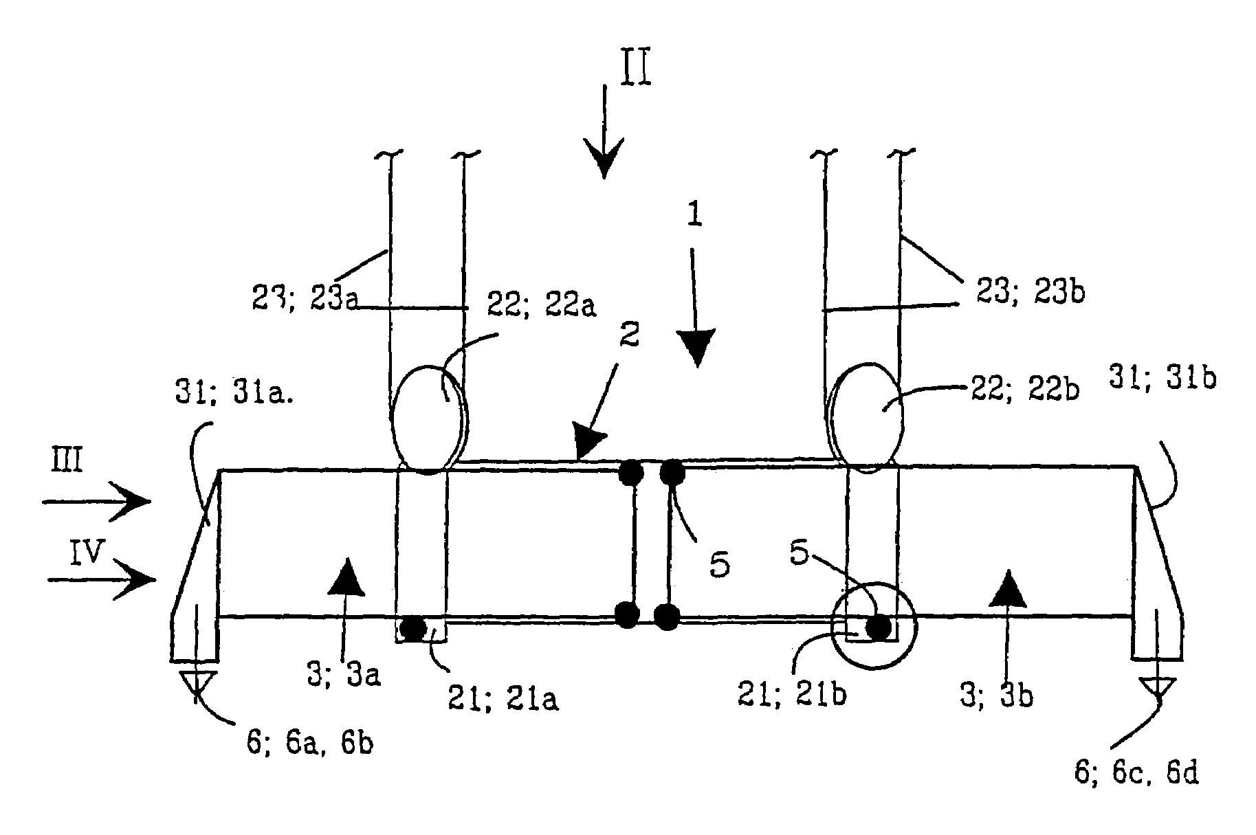
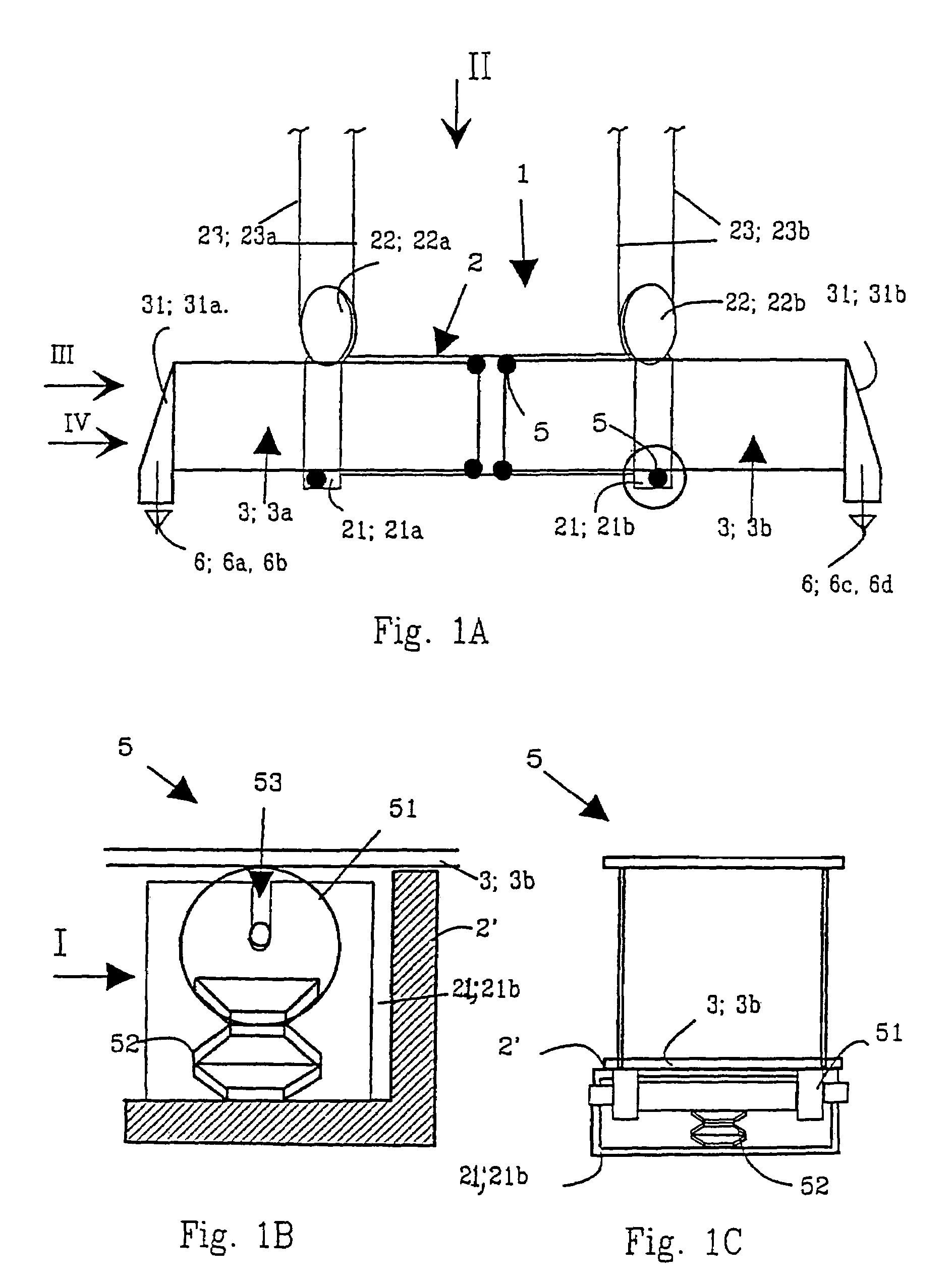
[0050]FIG. 1A shows the main parts of the spreader from the side. The spreader comprises the frame 2 with telescopic beams 3 moving telescopically inside. The ends of the telescopic beams are provided with twistlocks 6.

[0051]In FIGS. 1B and 1C, the detail encircled in FIG. 1 is shown enlarged and seen slightly from different directions. In FIG. 1B, the detail in question is shown from the same direction as in FIG. 1A; in FIG. 1C, this detail again is shown from the direction I in FIG. 1B. The detail shows the structure of the movement support 5 of the telescopic beam attached to the corner 21; 21a of the second frame.

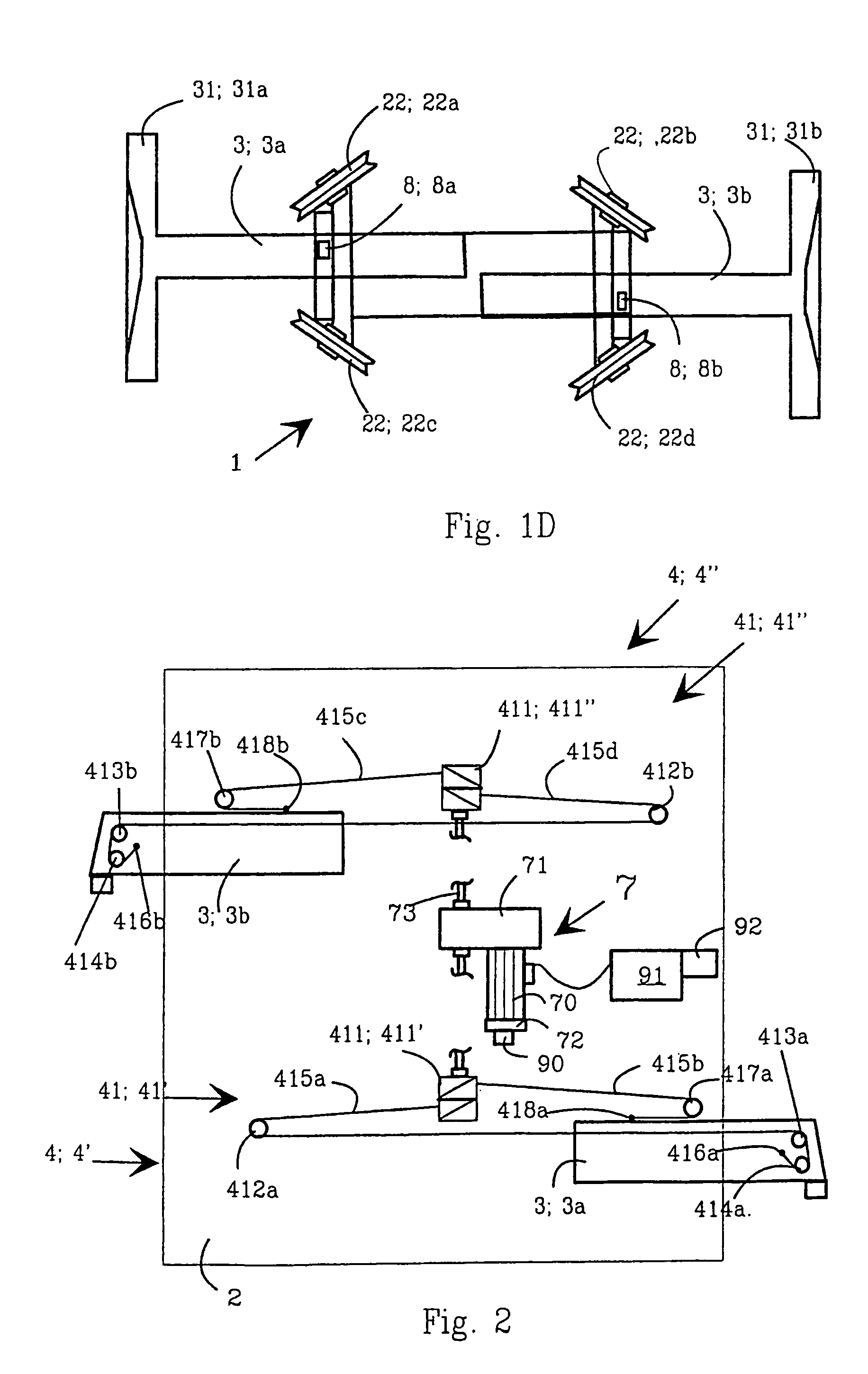
[0052]FIG. 1D shows in a more exact manner the way the telescopic beams 3 are placed in the frame 2. The figure al...


PUM


Abstract

A system and method for controlling the telescopic movements of two telescopic beams moving inside a spreader frame, and the locking movements of the twistlocks in the telescopic beams. The telescopic movement of the telescopic beams are held in position at a desired place in relation to the frame with locking members. The system has a joint multi-rope lever system for performing the telescopic movement of the telescopic beams and the locking movements of the twistlocks. The system has an actuator operating the multi-rope lever system. The system also includes a control system supervising and controlling the actuator and the lever system.

Description

FIELD OF THE INVENTION[0001]The invention relates to a system for controlling the telescopic movements of telescopic beams in a spreader, and the locking movements of twistlocks in telescopic beams.[0002]The invention also relates to a method for controlling the telescopic movements of telescopic beams in a spreader, and the locking movements of twistlocks in telescopic beams.BACKGROUND OF THE INVENTION[0003]A special spreader especially designed for the purpose is used for lifting containers. The spreader comprises a frame and two telescopic beams resting on the frame, the beams performing a telescopic movement, i.e. more exactly, a transfer movement in the direction of the longitudinal axis of the telescopic beams into and out of the spreader frame. Both the telescopic beams generally have two twistlocks. The telescopic beams grip the lifting attachments in the corners of the container with the twistlocks. As there are containers of several different lengths, i.e. the length may v...

Claims


Application Information

Patent Timeline
Patent Type & Authority Patents(United States)
IPC IPC(8): B66C1/66
CPCB66C1/663
Inventor JUSSILA, OVALIKAITURINMAKI, JARI
Owner KONECRANES GLOBAL
Why Eureka
Try Eureka