Solid state light engine optical system

a solid-state light engine and optical system technology, applied in the field of light and image projectors, can solve the problems of generating too much heat, affecting the quality of light, and a large number of expensive parts, and achieve the effects of reducing production costs, reducing production costs, and reducing production costs

Inactive Publication Date: 2006-12-26
QUBIC LIGHT CORP
View PDF10 Cites 59 Cited by
  • Summary
  • Abstract
  • Description
  • Claims
  • Application Information

AI Technical Summary

Benefits of technology

[0010]Additionally, light concentrators such as quad reflective, total internal reflection (TIR) differential, or edge ray concentrators, collectively known as non-imaging concentrators, used in reverse and hence called emitters may be used to collect and subsequently emit light from solid state sources with large areas in the illumination subsystem. The quad differential or edge ray concentrators may include four individually blended concentrators that are integrated side by side, centered on, and covering a quadrant of the solid state source. The shape of the perimeter of the end nearest the solid state source may also be described as a “clover” configuration. This configuration enables an efficient collection and emission optic with a substantially smaller size than a single concentrator covering the entire solid state source.
[0011]In one exemplary implementation, a quad TIR compound hyperbolic emitter (CHE) is used to collect and emit light from large LED die sizes and is composed of four individual TIR compound hyperbolic emitters blended side by side to cover the large LED die. Each CHE is centered on and covers a quadrant of the LED die enabling an efficient collection and emission optic much shorter and smaller than a single concentrator.
[0012]The output from a non-circular die , or a group of dies, may be more evenly captured and transmitted by orienting each dies corner at the overlap between each of the four CHEs forming the quad TIR CHE such as one having the clover configuration.

Problems solved by technology

However, prior art projectors have disadvantages in that they can be heavy, complex, or dim; can comprise a great number of expensive parts; be too large; generate too much heat; require cooling fans; make too much noise; or have short bulb life.

Method used


Image

  • Solid state light engine optical system
  • Solid state light engine optical system
  • Solid state light engine optical system

Examples


Embodiment Construction

[0028]Detailed descriptions are disclosed herein; however, it is to be understood that the disclosed embodiments are merely exemplary of the invention, which may be embodied in various forms. Therefore, specific structural and functional details disclosed herein are not to be interpreted as limiting, but merely as a basis for claims and as a representative basis for teaching one skilled in the art to variously employ the present invention in virtually any appropriately detailed structure.

[0029]Reference will now be made in detail to that disclosure, which is illustrated in the accompanying drawing (FIGS. 1–18).

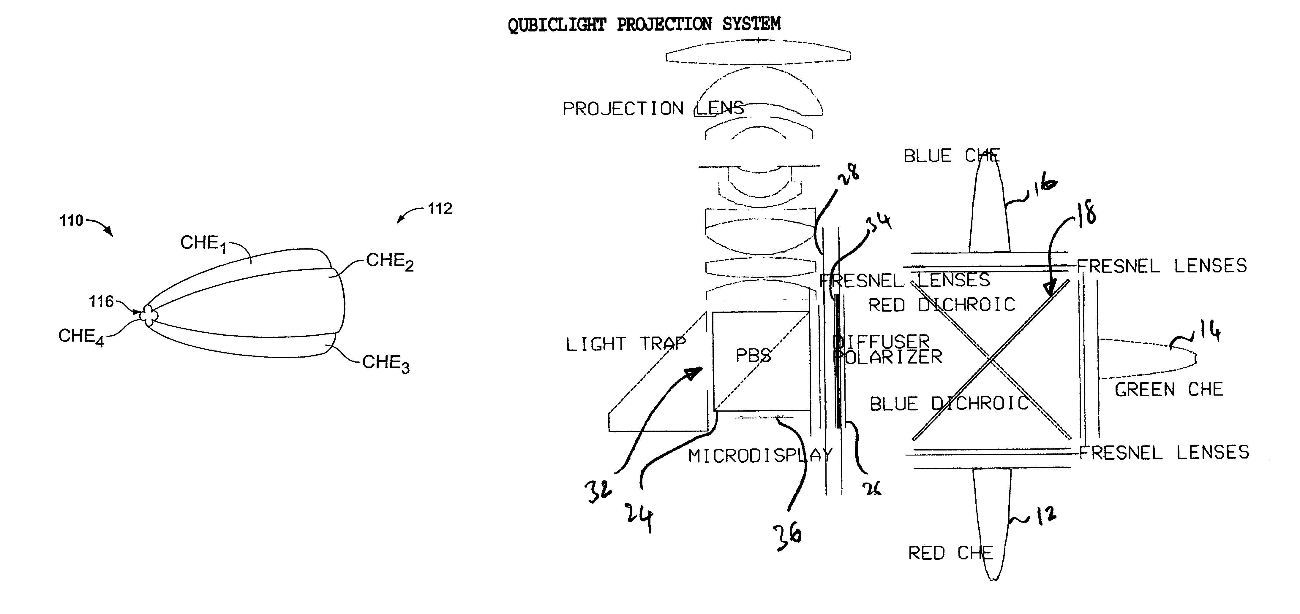
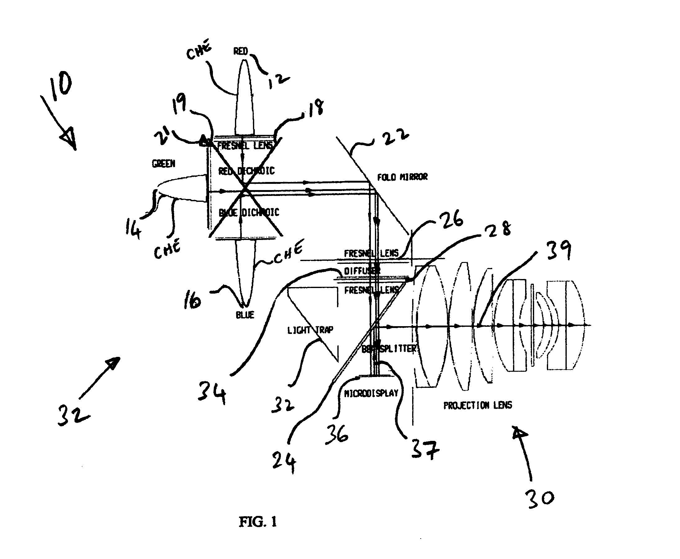
[0030]As shown in FIG. 1 the optical system 10 of is a solid-state projector consisting of an illumination subsystem 32 and a projection subsystem 30. The illumination subsystem 32 illuminates at least one micro-display 36 with light from a plurality of red 12, green 14, and blue 16 light emitting diodes (LEDs) arranged in separate color groups. The projection subsystem 30 ima...


PUM


Abstract

An optical system for use in projection based displays includes a plurality of solid state light sources associated with a plurality of total internal reflection based compound hyperbolic emitters, a graduated dichroic filter based device for homogenizing light output from the plurality of solid state light sources, a ferro-electric liquid crystal on silicon device for illumination with light output from the array of solid state light sources, and a polarization diffuser for homogenization of light at the ferro-electric liquid crystal on silicon device, wherein the polarization diffuser is positioned at a point in space, in the optical system, where the size of a beam of light transmitted from the graduated dichroic filter based device is substantially at a maximum.

Description

CROSS-REFERENCE TO RELATED APPLICATIONS[0001]The contents of this application are related to U.S. Provisional Application Ser. No. 60 / 465,732 (filed Apr. 24, 2003), entitled “Personal Theater Optical System” the contents of which are incorporated herein by reference in their entirety.BACKGROUND[0002]1. Field of the Invention[0003]The present invention relates to light and image projectors and particularly to illumination devices for projection displays.[0004]2. Description of the Background Art[0005]The prior art discloses various light sources and image projectors for viewing videos and images. The simplest light projector comprises a flashlight and a more complex device comprises an image projector with an incandescent light source such as in U.S. Pat. No. 6,227,669.[0006]However, prior art projectors have disadvantages in that they can be heavy, complex, or dim; can comprise a great number of expensive parts; be too large; generate too much heat; require cooling fans; make too mu...

Claims


Application Information

Patent Timeline
Patent Type & Authority Patents(United States)
IPC IPC(8): G03B21/26G03B21/28G02B17/02G02B19/00G02B27/14G02B27/28
CPCG02B17/02G02B27/1033G02B27/149G02B27/28H04N9/315G02B19/0066G02B19/0028
Inventor RUDA, MITCHELL C.STUHLINGER, TILMAN W.GARCIA, KEVIN J.
Owner QUBIC LIGHT CORP
Why Eureka
Try Eureka