Apparatus and method for determining the status of an electric power cable

a technology of underground residential distribution and status determination, applied in the direction of instruments, line-transmission details, indicating the presence of current/voltage, etc., can solve the problems of many live cables being misdiagnosed as dead, and the presence of extraneous unmapped urd cables b>20/b>, etc., to achieve the effect of easy and straightforward manner

Inactive Publication Date: 2006-12-26
PIESINGER GREGORY H
View PDF6 Cites 11 Cited by
  • Summary
  • Abstract
  • Description
  • Claims
  • Application Information

AI Technical Summary

Benefits of technology

[0035]Accordingly, it is an advantage of the present invention that an apparatus is provided for determining the status of an underground residential distribution (URD) cable.
[0036]It is another advantage of the present invention that an apparatus is provided that actively tests a URD cable for both a live and a dead status.
[0037]It is another advantage of the present invention that an apparatus is provided that determines the status of a URD cable while the worker is safely at a distance from the URD cable.
[0038]It is another advantage of the present invention that an apparatus is provided that displays results viewable at a distance.
[0039]It is another advantage of the present invention that an apparatus is provided that determines a quality of connection to a URD cable while determining the status thereof.
[0040]It is another advantage of the present invention that an apparatus is provided that determines the status of a URD cable in an easy and straightforward manner.

Problems solved by technology

This poses certain problems.
One problem is that there are often multiple URD cables 20 in a given trench, conduit, or raceway.
A problem exists in determining which of these multiple URD cables 20 is de-energized (i.e., “dead”).
Consequently, many live cables are misdiagnosed as being dead.
Another related problem is that, in a given dig, extraneous unmapped URD cables 20 may be present.
The spiking of a live URD cable 20 is undesirable for several reasons.
First, spiking a live URD cable 20 poses a risk to the worker, albeit a risk significantly less than the cutting of a live URD cable 20.
Second, tripping the circuit breaker causes an unnecessary power outage to all customers served by that URD cable 20.
Third, unnecessarily spiking a URD cable 20 necessitates a repair of that URD cable 20.
Spiking a live URD cable 20, therefore, is dangerous, costly, and time consuming.
All of these apparatuses suffer from one or more deficiencies.
A false-live result may cause the worker to backtrack and double-check the removal of power from the desired URD cable 20, may cause additional and unnecessary excavation, and may cause further labor and paperwork.
This may result in a waste of time and resources.
But a false-dead result, on the other hand, may lead to misidentification of the specific URD cable 20 to be cut and spliced.
As previously mentioned, spiking a live URD cable 20 is dangerous, costly, and time-consuming.
This is a dangerous presumption.
On the other hand, such an apparatus does not positively determine if URD cable 20 is dead.
This form of test therefore exhibits a high incidence of false-dead results.
Another problem with many apparatuses for determining the status of URD cables 20 is that they are cumbersome to use.
Because the URD cables 20 may carry high voltage (typically 7,200 volts), any procedure requiring direct manipulation of the cable is inherently dangerous.
A faulty or misidentified cable may expose the worker to high voltage, and potentially precipitate injury or death.
Additionally, all procedures requiring direct manipulation of the cable are cumbersome, costly, and time-consuming.
This repair is itself cumbersome, costly, and time-consuming.
Cumbersome and time-consuming procedures often inspire workers to shortcut the testing procedure.
This may lead to injury or death, as well as expensive and time-consuming error.
Such apparatuses are often difficult to maneuver from a distance.
Such careful manipulation is awkward and cumbersome to perform in the field, and inspires the worker to shortcut the testing procedure by making a minimum number of tests (often a single test, especially where a desired result is obtained) where a plurality of tests is required for positive results.
Since the URD cables carry high voltages at respectable currents, the environment in which the tests are performed is generally electrically noisy.
The combination of low signal strength and a noisy environment creates a tendency for such apparatuses to indicate false-live statuses.
This is especially true of those apparatuses having lengthy and or unshielded input lines.
But this would only lead to a less usable apparatus.
This poses a significant hazard in that a defective URD cable 20, or a penetration of an otherwise good URD cable 20, may cause the high voltage to be conducted over the line to a point outside the trench or raceway.
Once high voltage is out of the trench or raceway, there is a danger that an individual may come into contact with the high voltage and suffer injury or death as a result.
In addition, this high voltage may find a path through equipment which may subsequently become damaged or destroyed.

Method used


Image

  • Apparatus and method for determining the status of an electric power cable
  • Apparatus and method for determining the status of an electric power cable
  • Apparatus and method for determining the status of an electric power cable

Examples


Embodiment Construction

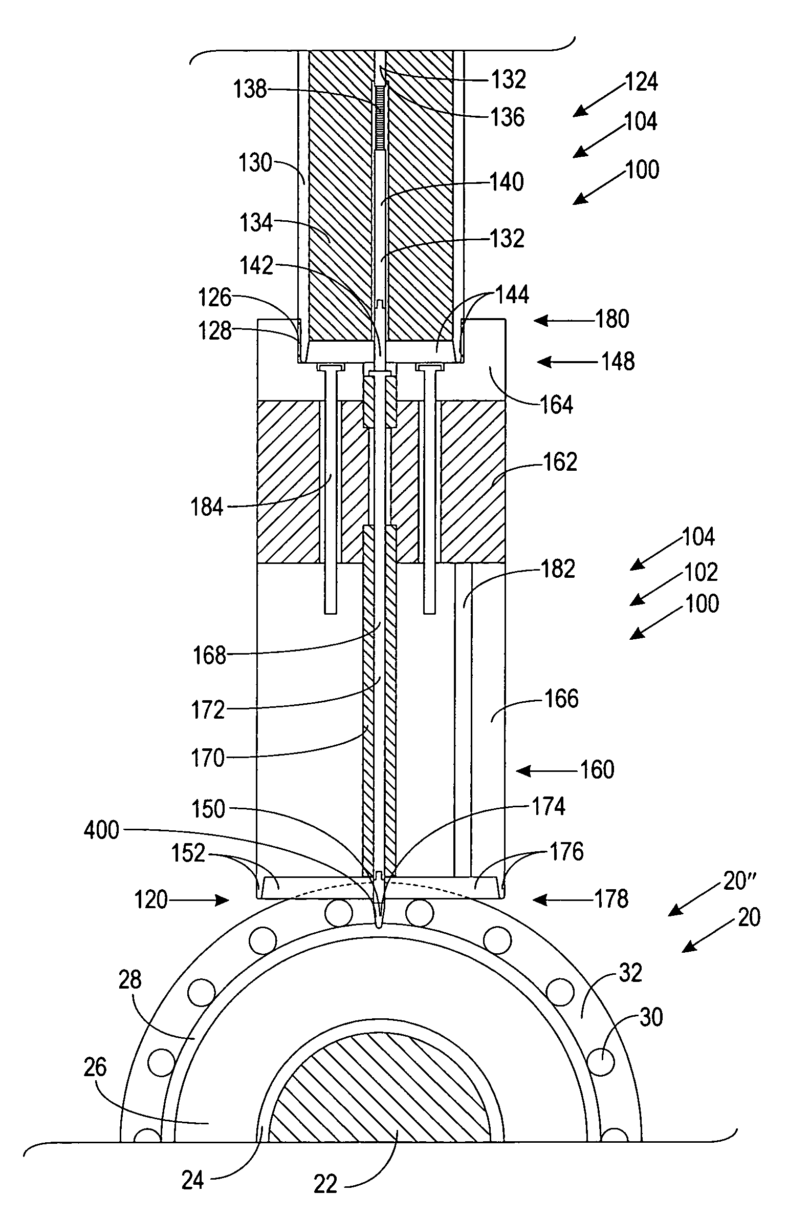
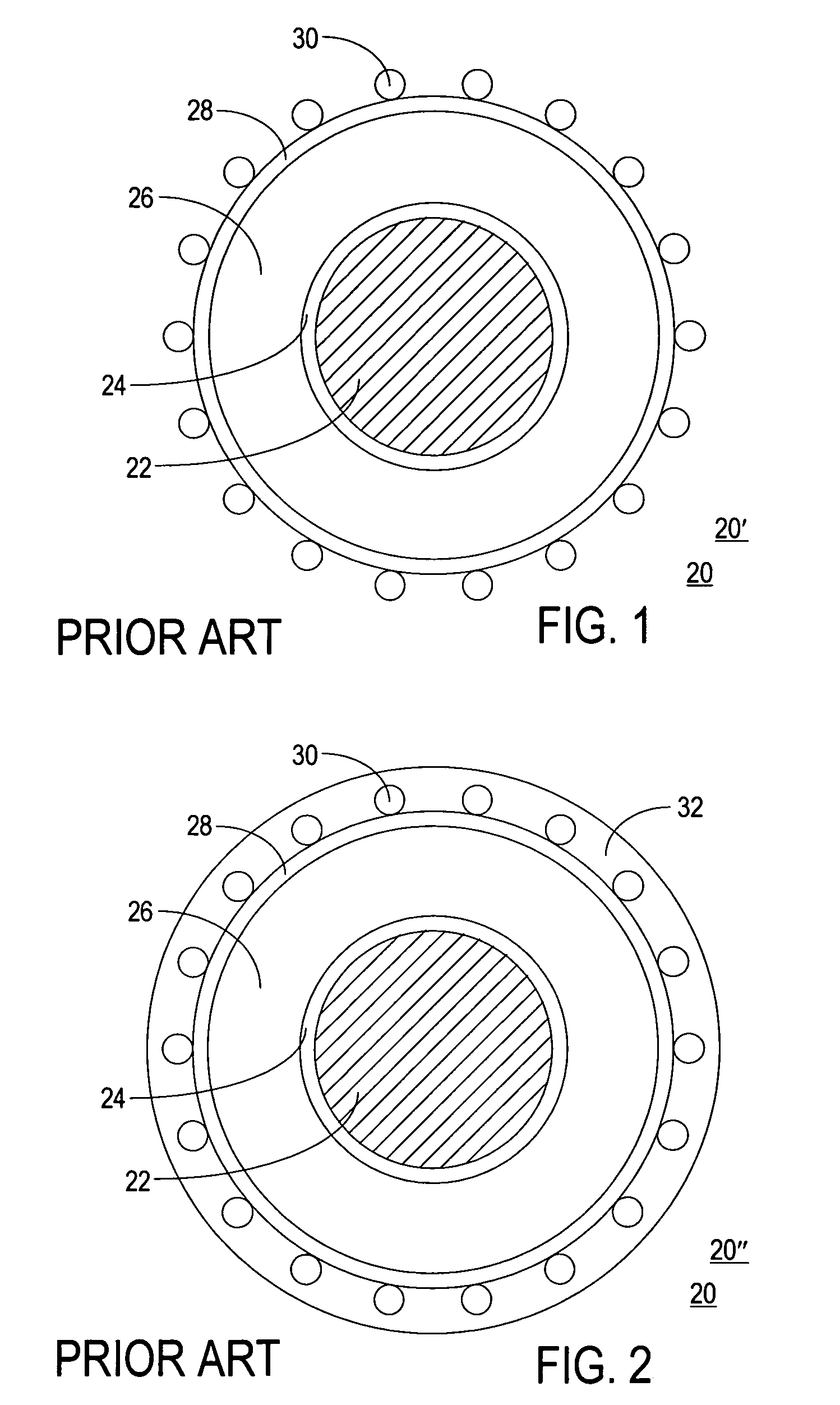
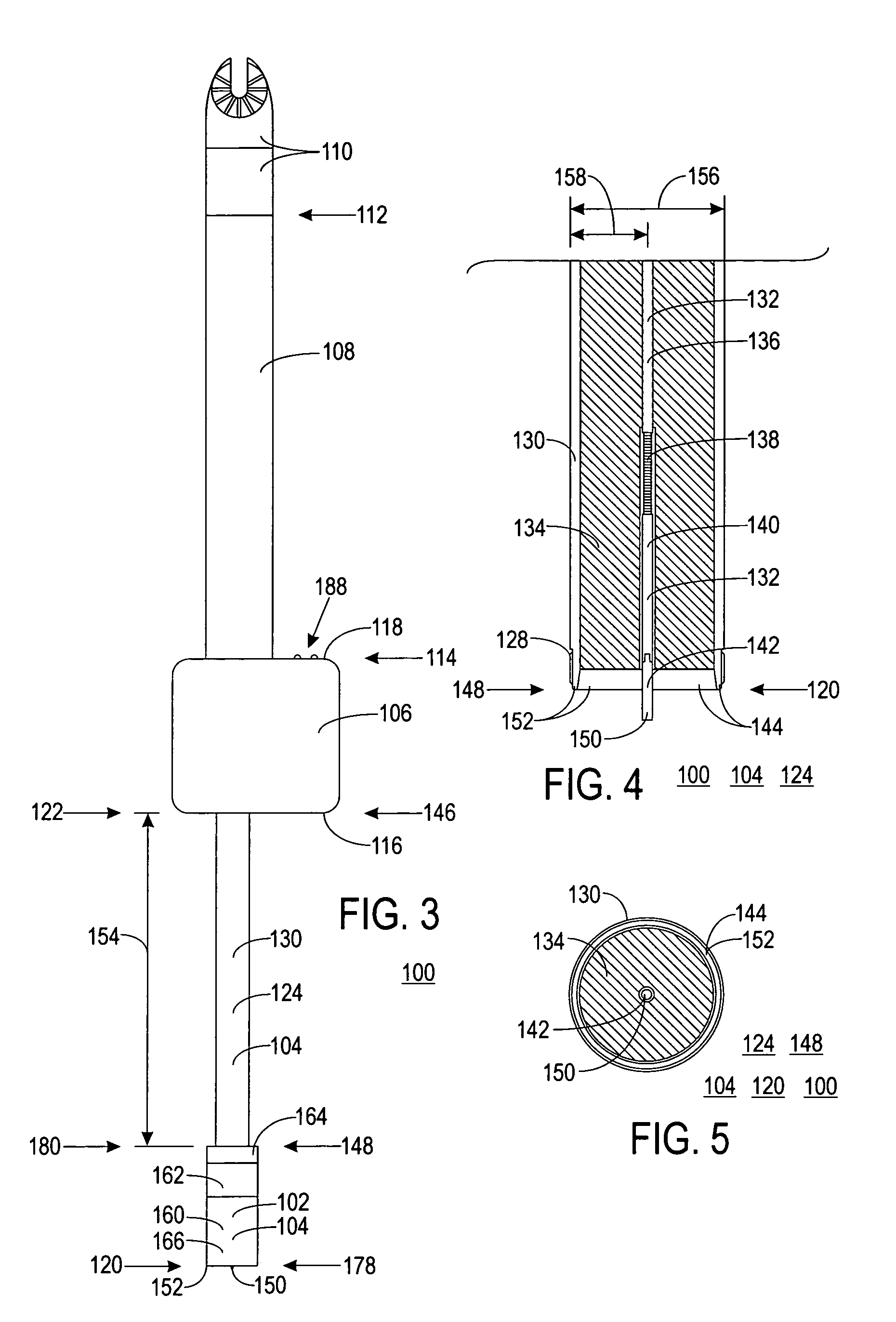
[0067]FIGS. 1 and 2 show cross-sectional views of typical underground residential distribution (URD) cables 20, with FIG. 1 showing an unjacketed URD cable 20′ and FIG. 2 a jacketed URD cable 20″. FIG. 3 shows a side view of an apparatus 100 that determines the status of a URD cable 20 in accordance with a preferred embodiment of the present invention. FIG. 4 shows a cross-sectional side view and FIG. 5 an end view of a portion of apparatus 100 for use with unjacketed URD cable 20′ in accordance with a preferred embodiment of the present invention. FIG. 6 shows a side view and FIG. 7 an end view of a melt unit 102 for apparatus 100 for use with jacketed URD cable 20″ in accordance with a preferred embodiment of the present invention. The following discussion refers to FIGS. 1 through 7.

[0068]Status determination apparatus 100 is a probing device configured to engage URD cable 20 and determine the status thereof. Apparatus 100 is a rigid structure made up of a probe 104 to which is c...


PUM


Abstract

An apparatus (100) and method (300) for determining the status of a electric cable (20) is provided. The apparatus (100) rigidly includes a probe (104) having coaxial contacts (150, 152) and including a melt unit (102) configured to melt an insulating jacket (32) of the cable (20), an instrumentation unit (106) coupled to the probe (104) and housing a cable analysis circuit (186), a status display unit (188) coupled to the instrumentation unit (106), an insulated shank (108) coupled to the instrumentation unit (106), and a hotstick adapter (110) coupled to the insulated shank (108). The cable analysis circuit (186) includes a connection determination circuit (200) configured to determine if an electrical connection between the probe (104) and the cable (20) is a valid connection, and a status determination circuit (222) configured to determine the status of the cable (20) while the electrical connection is a valid connection. The status display unit (188) includes a plurality of visual indicators (236) configured to impart connection condition and cable status to the user.

Description

RELATED INVENTION[0001]This application is a continuation-in-part (CIP) of application Ser. No. 10 / 778,288 filed on Feb. 11, 2004, now abandoned which is hereby incorporated by reference.[0002]The present invention claims benefit under 35 U.S.C. §119(e) to “Apparatus and Method for Probing The Center Conductor Electric Field of Jacketed and Unjacketed Underground Distribution Cable,” U.S. Provisional Patent Application Ser. No. 60 / 559,314 filed 2 Apr. 2004, which is incorporated by reference herein.TECHNICAL FIELD OF THE INVENTION[0003]The present invention relates to the field of electric power distribution networks. More specifically, the present invention relates to determining the status of underground residential distribution power cables.BACKGROUND OF THE INVENTION[0004]Electric power distribution networks are used by the electric utilities to deliver electricity from generating plants to customers. Although the actual distribution voltages will vary from utility to utility, i...

Claims


Application Information

Patent Timeline
Patent Type & Authority Patents(United States)
IPC IPC(8): G01R31/02G01R19/00G01R19/145G01R31/58H01H31/02H04B3/46
CPCG01R19/145G01R31/021G01R31/086G01R31/025G01R31/58G01R31/52
Inventor PIESINGER, GREGORY H.
Owner PIESINGER GREGORY H
Why Eureka
Try Eureka