Reflective imaging optical system, exposure apparatus, and method for producing device

a technology of catoptric imaging and optical system, which is applied in the direction of mirrors, instruments, printers, etc., can solve the problems of reducing the throughput of the apparatus, increasing the light loss, etc., and achieving the effect of ensuring the distance between an illumination area and the optical axis, and reducing the illumination loss

Active Publication Date: 2012-03-15
NIKON CORP
View PDF2 Cites 11 Cited by
  • Summary
  • Abstract
  • Description
  • Claims
  • Application Information

AI Technical Summary

Benefits of technology

[0019]In the reflective imaging optical system, according to an aspect of the present invention, which is provided as the optical system of the far pupil type constructed of eight pieces of mirrors, the required condition is fulfilled by the distance PD which is provided along the optical axis between the entrance pupil and the first plane, the distance TT which is provided along the optical axis between the first plane and the second plane, and the angle of incidence R of the main light beam which comes (is allowed to come) into the first plane. Accordingly, it is possible to realize the reflective imaging optical system of the far pupil type having a large numerical aperture. Further, it is possible to realize an optical system in which the aberration is satisfactorily corrected.
[0020]In the reflective imaging optical system, according to another aspect of the present invention, which is provided as the optical system of the far pupil type constructed of eight pieces of mirrors, the first to third reflecting mirrors are arranged on a side of the predetermined area with respect to the optical axis. Accordingly, it is possible to correct the aberration satisfactorily. Further, it is possible to secure the distance between an illumination area and the optical axis to be relatively great, which consequently makes it possible to secure the entrance pupil distance PD with a predetermined size or length.
[0021]In a case that the reflective imaging optical system of the present invention is applied to the exposure apparatus, the EUV light (EUV light beam), which has a wavelength of, for example, 5 nm to 40 nm, can be used as the exposure light (exposure light beam). In this case, the pattern of the mask can be projected onto the photosensitive substrate to expose the photosensitive substrate therewith at a high resolution by relatively moving the photosensitive substrate and the pattern of the mask to be transferred relative to the reflective imaging optical system. As a result, a highly accurate device can be produced under the satisfactory exposure condition by using the scanning type exposure apparatus having a large resolving power.

Problems solved by technology

However, increase in the number of the mirror leads to increase in the light loss (optical loss), which in turn lowers the throughput of the apparatus.

Method used


Image

  • Reflective imaging optical system, exposure apparatus, and method for producing device
  • Reflective imaging optical system, exposure apparatus, and method for producing device
  • Reflective imaging optical system, exposure apparatus, and method for producing device

Examples


first embodiment

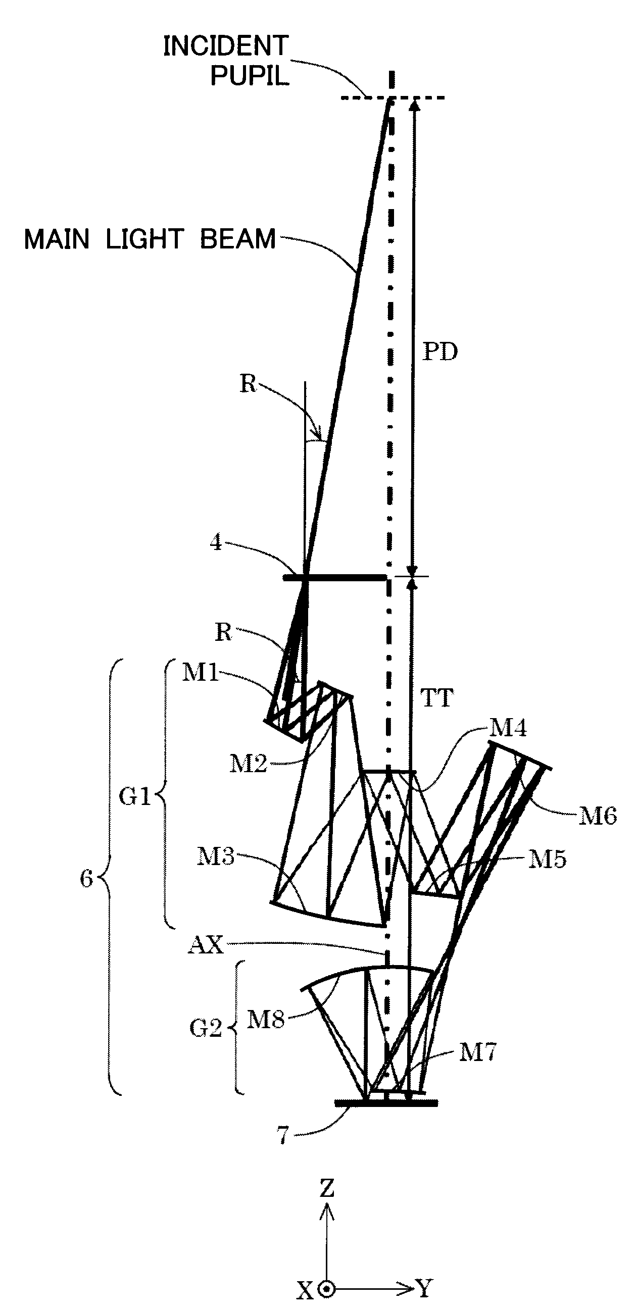
[0058]FIG. 4 shows a construction of a reflective imaging optical system 6 according to a first embodiment of the embodiment of the present invention. With reference to FIG. 4, in the reflective imaging optical system 6 of the first embodiment, the light from the mask 4 is successively reflected by the concave reflecting surface of the first reflecting mirror M1, the convex reflecting surface of the second reflecting mirror M2, the concave reflecting surface of the third reflecting mirror M3, and the convex reflecting surface of the fourth reflecting mirror M4, the convex reflecting surface of the fifth reflecting mirror M5 and the concave reflecting surface of the sixth reflecting mirror M6 and then the intermediate image of the mask pattern is formed. The light from the intermediate image formed via the first reflective optical system G1 is successively reflected by the convex reflecting surface of the seventh reflecting mirror M7 and the concave reflecting surface of the eighth r...

second embodiment

[0063]FIG. 5 shows a construction of a reflective imaging optical system 6 according to a second embodiment of the embodiment of the present invention. With reference to FIG. 5, the light from the mask 4 is also successively reflected by the concave reflecting surface of the first reflecting mirror M1, the convex reflecting surface of the second reflecting mirror M2, the concave reflecting surface of the third reflecting mirror M3, the convex reflecting surface of the fourth reflecting mirror M4, the convex reflecting surface of the fifth reflecting mirror M5, and the concave reflecting surface of the sixth reflecting mirror M6 and then the intermediate image of the mask pattern is formed also in the reflective imaging optical system 6 according to the second embodiment, in the same manner as in the first embodiment. The light from the intermediate image formed via the first reflective optical system G1 is successively reflected by the convex reflecting surface of the seventh reflec...

third embodiment

[0065]FIG. 6 shows a construction of a reflective imaging optical system according to a third embodiment of the embodiment of the present invention. With reference to FIG. 6, the light from the mask 4 is successively reflected by the convex reflecting surface of the first reflecting mirror M1, the concave reflecting surface of the second reflecting mirror M2, the convex reflecting surface of the third reflecting mirror M3, the concave reflecting surface of the fourth reflecting mirror M4, the convex reflecting surface of the fifth reflecting mirror M5, and the concave reflecting surface of the sixth reflecting mirror M6 and then the intermediate image of the mask pattern is formed in the reflective imaging optical system 6 of the third embodiment. The light from the intermediate image formed via the first reflective optical system G1 is successively reflected by the convex reflecting surface of the seventh reflecting mirror M7 and the concave reflecting surface of the eighth reflect...


PUM


Abstract

An reflective imaging optical system of the far pupil type, which is applicable to an exposure apparatus using for example the EUV light, forms on a second plane an image of a predetermined area on a first plane and is provided with first to eighth reflecting mirrors arranged in an order of reflection from the first plane toward the second plane. An entrance pupil of reflective imaging optical system is positioned on a side opposite to the reflective imaging optical system with the first plane intervening therebetween; and the following condition is fulfilled provided that PD represents a distance along an optical axis between the entrance pupil and the first plane, TT represents a distance along the optical axis between the first plane and the second plane, and R represents an angle of incidence of a main light beam coming into the first plane: −14.3<(PD / TT) / R<−2.5.

Description

CROSS-REFERENCE TO RELATED APPLICATION[0001]This application claims the benefit of priority of U.S. Provisional Application Ser. No. 61 / 381,586 filed on Sep. 10, 2010, and the disclosure of U.S. Provisional Application Ser. No. 61 / 381,586 is incorporated herein by reference in its entirety.BACKGROUND OF THE INVENTION[0002]1. Field of the Invention[0003]The present invention relates to a reflective (catoptric) imaging optical system, an exposure apparatus, and a method for producing a device. More specifically, the present invention relates to a reflective imaging optical system preferably useable for an exposure apparatus which uses, for example, the EUV light (EUV light beam) and transfers, onto a photosensitive substrate, a circuit pattern on a mask for example in accordance with the mirror projection system.[0004]2. Description of the Related Art[0005]Attention is directed to an EUVL (Extreme UltraViolet Lithography) exposure apparatus which uses the EUV (Extreme UltraViolet) lig...

Claims


Application Information

Patent Timeline
Patent Type & Authority Applications(United States)
IPC IPC(8): G03B27/54G02B17/06
CPCG03F7/70233
Inventor KAWABE, YOSHIO
Owner NIKON CORP
Why Eureka
Try Eureka