Indexer, indexer retrofit kit and method of use thereof

a technology for indexers and retrofit kits, which is applied in the direction of lighting and heating apparatus, manufacturing tools, instruments, etc., can solve the problems of serious injury to operators, inability to properly direct high-pressure water, and affecting the operation of indexers, so as to achieve quick and easy setup

Active Publication Date: 2019-09-10
TERYDON
View PDF68 Cites 10 Cited by
  • Summary
  • Abstract
  • Description
  • Claims
  • Application Information

AI Technical Summary

Benefits of technology

[0012]The indexer system disclosed herein is useful for moving a nozzle of a water-jet cleaning apparatus quickly and precisely from one opening on a tube bundle to another. The system may include an indexer that enables the operator to be located remote, i.e., a distance away, from the nozzles and therefore at a safer distance from the high pressure water-jet utilized for cleaning. Still further, the indexer disclosed herein may be operable via an electronic device such as a tablet or smart phone. Furthermore, the electronic device may be provided with special programming that is used for controlling the operation of the indexer. The operator may perform a number of quick and simple set up maneuvers with the indexer system and the programming stores the relative distance measurements between two adjacent row and column openings on the face plate. The programming maps out the pattern of the openings in the face plate and during a subsequent cleaning operation, the derived relative distance measurements may be used to react to operator position requests. In other words, the stored information aids the operator in progressively moving the cleaning system's nozzles from one opening in the heat exchanger face plate to another until all tubes in the heat exchanger have been cleaned. This may all be accomplished without putting the operator at unnecessary risk.

Problems solved by technology

After a heat exchanger has been used for some time the bores of the heat exchanger tubes tend to become partially or completely blocked with material that has been deposited therein.
One of the issues of cleaning heat exchanger tubes with a high pressure water-jet is that the high-pressure stream of water has to be directed reasonably accurately into the opening of each tube.
The deflected water-jet may seriously injure the operator or cause damage to other objects in the vicinity of the heat exchanger simply because of the pressure under which the water is delivered to the nozzles on the cleaning apparatus.
It is therefore problematic to set up a water-jet cleaning apparatus to accurately aim the water jets into the tube openings.
A lot of time-consuming manual adjustment has to be undertaken to make sure the tubes are all adequately cleaned.
It is even more problematic to move a cleaning apparatus from one heat exchanger to another without expending quite a long time in setting-up the cleaning apparatus on both pieces of equipment.

Method used


Image

  • Indexer, indexer retrofit kit and method of use thereof
  • Indexer, indexer retrofit kit and method of use thereof
  • Indexer, indexer retrofit kit and method of use thereof

Examples


Embodiment Construction

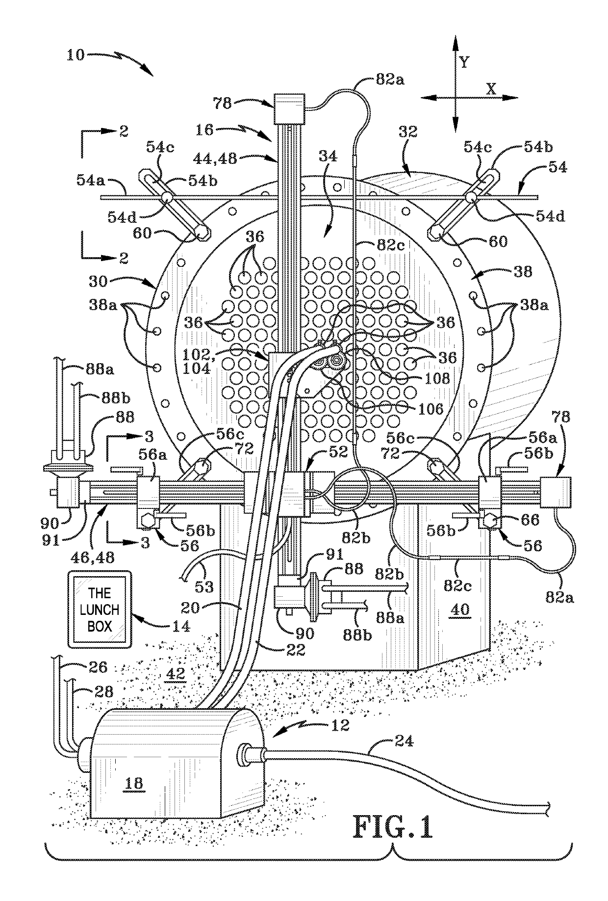
[0066]FIG. 1 shows, in the upper right hand corner thereof, a symbol to represent directions utilized in the description that follows. The symbol shows an X-axis to represent a horizontal axis or direction and a Y-axis to represent a vertical axis or direction The X-axis and Y-axis are oriented at right angles to each other.

[0067]Referring to FIGS. 1-14, there is shown a water-jet cleaning system in accordance with an aspect of the present disclosure, generally indicated at 10. System 10 may include a water delivery system 12 for providing water for a cleaning operation, a communication device 14 and an indexer 16 in accordance with the aspect of the present disclosure. Communication device 14 may be used to control and operate indexer 16 and water delivery system 12. While system 10 is described herein as being useful for cleaning heat exchanger tubes, it will be understood by those skilled in the art that system 10 may be used for a wide variety of other purposes. An operator usin...


PUM


Abstract

A system and method for cleaning of heat exchanger tubes including an assembly, an indexer and a communication device provided with specialized software and programming. The indexer includes orthogonally arranged first and second arms. A trolley and sensors are provided on the indexer arms. One or more lances are provided on the trolley to deliver water jets into the openings. Sensors measure displacement as the trolley is moved relative to the heat exchanger's face plate. An operator controls the system from a distance away using the communication device. During setup, the pattern of the face plate is learned and mapped utilizing information from the sensors as one of the inputs. This information is utilized to help navigate the face plate during a subsequent cleaning operation. A kit for retrofitting existing X-Y indexers is also disclosed.

Description

CROSS REFERENCE TO RELATED APPLICATIONS[0001]This application is a Continuation-in-Part of U.S. patent application Ser. No. 14 / 204,265 filed Mar. 11, 2014 now U.S. Pat. No. 10,265,834 which claims the benefit of U.S. Provisional Patent Application Ser. No. 61 / 821,433 filed May 9, 2013.[0002]This application is also a Continuation-in-Part of U.S. patent application Ser. No. 14 / 204,350 filed Mar. 11, 2014 now U.S. Pat. No. 10,040,169 which claims the benefit of U.S. Provisional Patent Application Ser. No. 61 / 821,433 filed May 9, 2013.[0003]This application is also a Continuation-in-Part of U.S. patent application Ser. No. 14 / 204,451, filed Mar. 11, 2014 now abandoned which claims the benefit of U.S. Provisional Patent Application Ser. No. 61 / 821,433 filed May 9, 2013.[0004]This application also claims the benefit of U.S. Provisional Patent Application Ser. No. 62 / 381,390, filed Aug. 30, 2016.[0005]The entire disclosures of the above-listed applications are all incorporated herein by r...

Claims


Application Information

Patent Timeline
Patent Type & Authority Patents(United States)
IPC IPC(8): F28G15/00B24C7/00G06F3/0488B24C3/32F28G15/02F28G1/16F28G15/04
CPCF28G15/003B24C3/327B24C7/0015G06F3/04886F28G15/02F28G15/04F28G1/163
Inventor GROMES, SR., TERRY D.GROMES, JR., TERRY D.GROMES, KRISTEN E.SHOCKEY, JR., JON M.EAST, GORDON W.JACKSON, WILLIAM C.
Owner TERYDON
Why Eureka
Try Eureka