Apparatus and method for safeguarding an automatically operating machine

Active Publication Date: 2016-02-11
PILZ (COMPANY)
View PDF3 Cites 13 Cited by
  • Summary
  • Abstract
  • Description
  • Claims
  • Application Information

AI Technical Summary

Benefits of technology

[0021]It is an object to specify an apparatus and a method of the aforementioned type that enable, in a very simple and efficient manner, the flexible presence of persons in the hazardous zone of an automatically operating machine, wherein the safeguarding of the machine and the necessary failure safety f

Problems solved by technology

With modern industrial robots that move at considerable speeds, collisions generally result in serious damage, both to the robots and to the workpieces being handled by the same.
This can result in costly production outages.
The installation of such safety devices is however rather expensive and the safety devices require a lot of space around a hazardous machine.
Moreover, such safety devices are not very flexible when it comes to adapting the safeguarding of the hazardous working area to different operating situations of the machine.
A great challenge for such methods and apparatuses is that the already complex image processing has to be implemented fail-safe in the sense of relevant standards for machine safety, in particular EN 954-1 (obsolete), EN ISO 13849-1, IEC 61508 and EN ISO 13855, so that such an apparatus can actually also be used for safeguarding a hazardous machine.
A failure of the apparatus itself may not result in the safeguarding of the machine being lost.
As a result the required safety level can indeed be guaranteed, but this takes up a great deal of space.
This would thus also make it difficult to install a plurality of robots adjacent to each other in a relatively small space, which would prove di

Method used


Image

  • Apparatus and method for safeguarding an automatically operating machine
  • Apparatus and method for safeguarding an automatically operating machine
  • Apparatus and method for safeguarding an automatically operating machine

Examples


Embodiment Construction

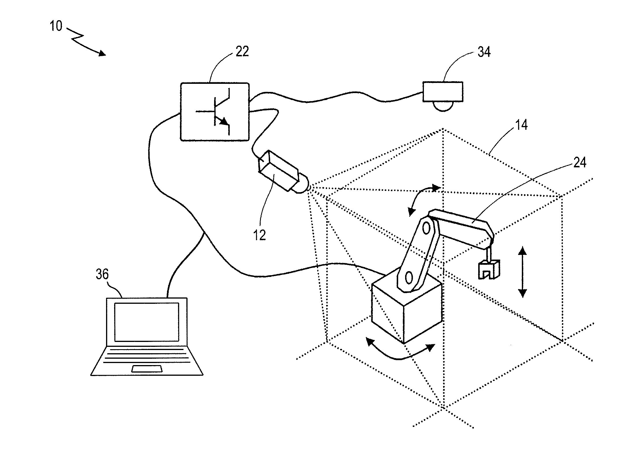
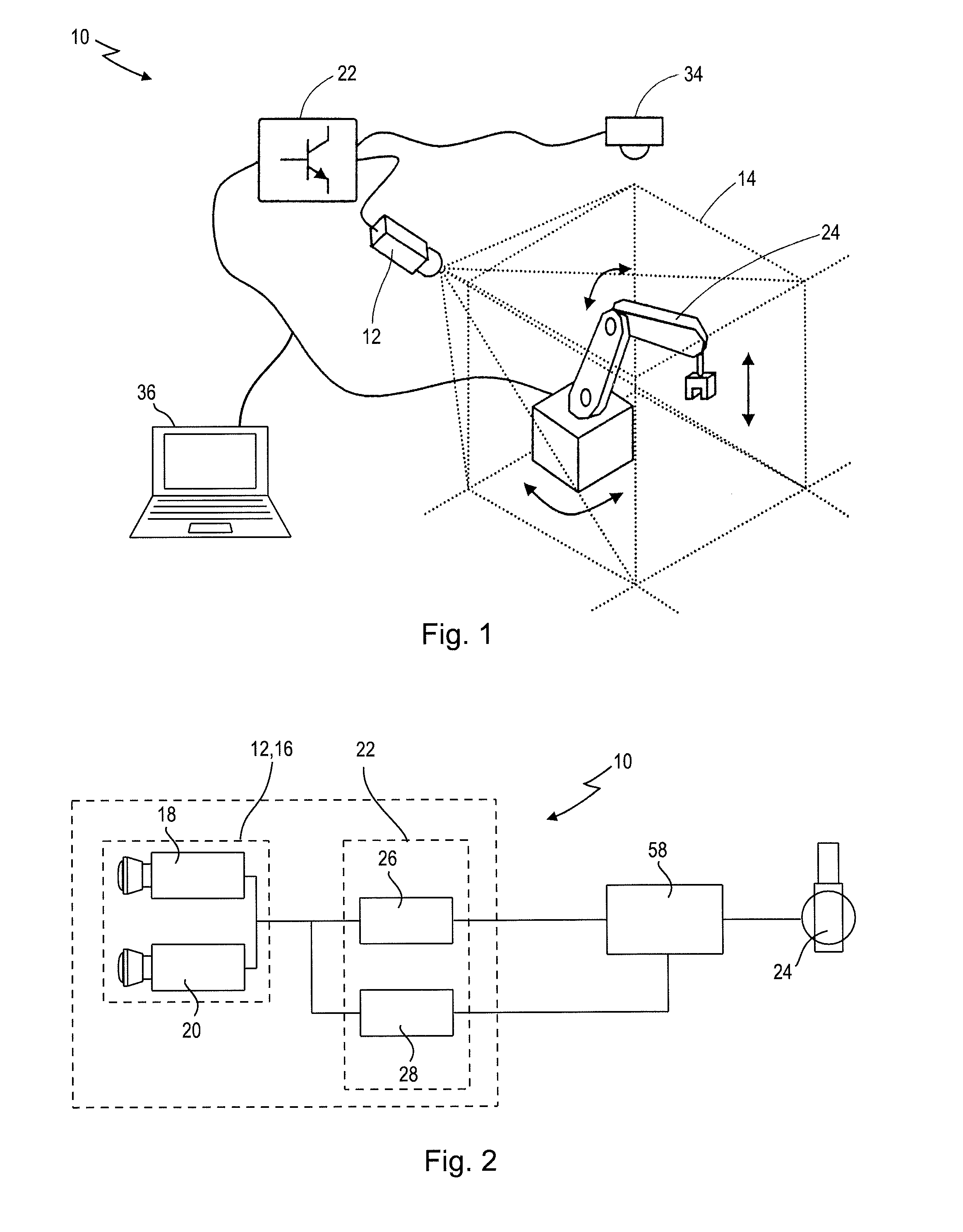
[0070]In FIGS. 1 and 2, a preferred exemplary embodiment of the new apparatus in its entirety is denoted by the reference numeral 10.

[0071]The apparatus 10 contains at least one sensor unit 12, which is designed to monitor a spatial area or monitoring area 14 in which an automatically operating system or machine, in this case a robot 24, is disposed. For this purpose, the sensor unit 12 preferably comprises a camera system 16 that is oriented towards the monitoring area 14. The camera system 16 is preferably configured in the form of a stereo camera system comprising at least a first camera 18 and a second camera 20. The cameras 18, 20 provide two slightly mutually offset images of the monitoring area to be safeguarded 14. Because of the offset of the cameras 18, 20 relative to each other and using trigonometric relationships, the distance from the sensor unit 12 to objects in the monitoring area 14 can be determined using the camera images. A preferred sensor unit of this type is d...


PUM


Abstract

An apparatus for safeguarding a monitoring area, in which an automatically operating machine is disposed, comprises: (i) a sensor unit including a camera system for producing images of the monitoring area; (ii) a configuration unit for defining first and second protection areas; and (iii) an evaluation unit for triggering a safety-related function. The first protection area is at a first distance from the machine and the second protection area is at a second greater distance from the machine. The sensor unit monitors both the first protection area and the second protection area. The evaluation unit analyzes the images produced by the camera system so as to evaluate both (i) whether a machine element of the machine enters the first protection area as well as (ii) whether a foreign object enters the second protection area. The evaluation unit triggers the safety-related function if at least one of these events occurs.

Description

CROSS-REFERENCES TO RELATED APPLICATIONS[0001]This application is a continuation of international patent application PCT / EP2014 / 057572, filed on Apr. 15, 2014 designating the U.S., which international patent application has been published in German language and claims priority from German patent application DE 10 2013 104 265.1, filed on Apr. 26, 2013. The entire contents of these priority applications are incorporated herein by reference.BACKGROUND OF THE DISCLOSURE[0002]This disclosure relates to an apparatus for safeguarding a monitoring area in which an automatically operating machine is disposed, with a sensor unit for monitoring the monitoring area, with a configuration unit for defining at least one first and one second protection area, and with an evaluation unit for triggering a safety-related function.[0003]The disclosure further relates to a corresponding method and a corresponding computer program for safeguarding a monitoring area in which an automatically operating mac...

Claims


Application Information

Patent Timeline
IPC IPC(8): F16P3/14G05B9/02
CPCG05B9/02F16P3/142
Inventor MERX, JOACHIM
Owner PILZ (COMPANY)
Why Eureka
Try Eureka