Electroluminescence display apparatus
- Summary
- Abstract
- Description
- Claims
- Application Information
AI Technical Summary
Benefits of technology
Problems solved by technology
Method used
Image

Examples
Embodiment Construction
[0035]A driving method for an EL display apparatus of the present invention is described hereinafter.
[0036]FIG. 6 is a block diagram of a column driver.
[0037]The column driver comprises the shift register 13 for inputting the data DATA for each column according to the shift clock CLK and the latch circuit 14 for latching in accordance with the latch pulse the data DATA that was input by the shift register 13. The driving signals COL1, COL2, COL3, . . . , COLm are respectively output to the column electrodes col1, col2, col3, . . . , colm from the latch circuit 14.
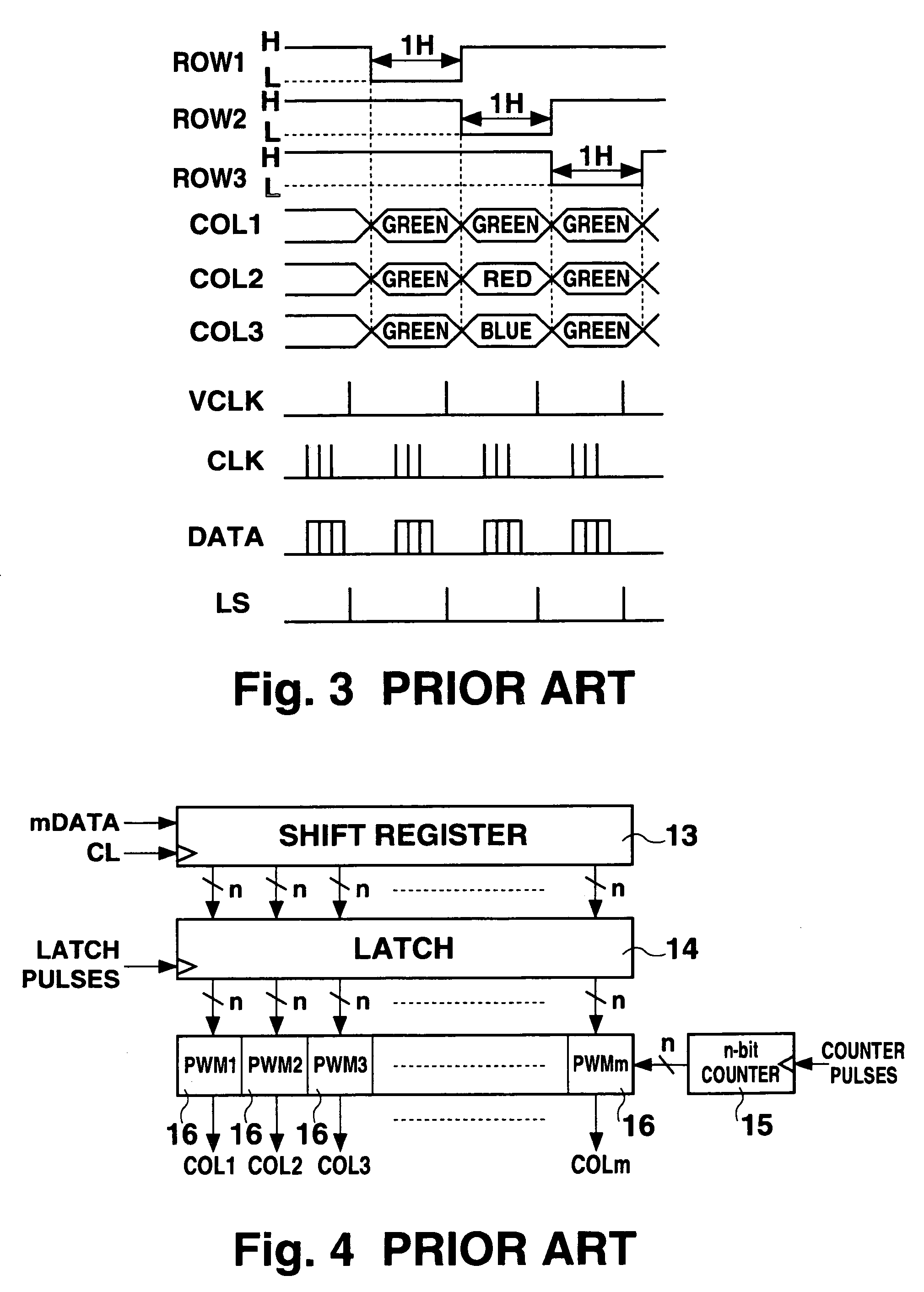
[0038]Compared to the column driver of the prior art shown in FIG. 4, the organic EL display apparatus of the present invention obviates the pulse width modulation circuits. Therefore, compared to the extreme complexity as in the column driver of the organic EL display apparatus of the prior art, the column driver of the organic EL display apparatus of the present invention can be designed to have an extremely simple config...
PUM
 Abstract
Description
Claims
Application Information
 - Generate Ideas
- Intellectual Property
- Life Sciences
- Materials
- Tech Scout
- Unparalleled Data Quality
- Higher Quality Content
- 60% Fewer Hallucinations
Browse by: Latest US Patents, China's latest patents, Technical Efficacy Thesaurus, Application Domain, Technology Topic, Popular Technical Reports.
© 2025 PatSnap. All rights reserved.Legal|Privacy policy|Modern Slavery Act Transparency Statement|Sitemap|About US| Contact US: help@patsnap.com