Multi-channel filtering system for transceiver architectures

a filtering system and transceiver technology, applied in the field of communication systems, can solve the problems of poor quality or drop of connections, critical limitation or critical limitation of destination receivers in their ability to process intended signals accurately, and achieve the effect of maximizing communication bandwidth

Inactive Publication Date: 2006-12-26
SIERRA MONOLITHICS INC
View PDF15 Cites 13 Cited by
  • Summary
  • Abstract
  • Description
  • Claims
  • Application Information

AI Technical Summary

Benefits of technology

[0006]The present invention provides a multi-channel filtering system and transceiver architecture which allows for a variable transmission and reception bandwidth. The variable transmission and reception rates enable the transceiver to combat adjacent channel interference when present, and to maximize the communication bandwidth when the spectrum is relatively free of adjacent channel interference.

Problems solved by technology

Present day communication systems are often limited in their reliability and speed by adjacent channel interference.
Adjacent channel interference, or “spectral crowding” as it is referred to in wireless communication systems, occurs when one or more received signals occur adjacent to the intended signal, the adjacent signal's proximity and / or signal strength relative to the intended signal being such that the destination receiver is critically limited or unable to process the intended signal accurately.
The problem often results in poor quality or dropped connections when a large number of users attempt to use the particular system's available bandwidth, as each user provides a potentially interfering signal to the other's intended signal.
The conventional transceiver 100 does not provide a solution to the adjacent channel interference problem, as it employs a single filter 134 which may be too wide in some circumstances, and too narrow in others.
For example, when the conventional transceiver 100 is operated in an environment or during a time when there are many adjacent channel users, the filter 136 may be too wide, and not provide the requisite amount of adjacent channel rejection during reception.
During other times when adjacent bands are relatively free, the filter 136 may be too narrow, limiting the communication rate unnecessarily.

Method used


Image

  • Multi-channel filtering system for transceiver architectures
  • Multi-channel filtering system for transceiver architectures
  • Multi-channel filtering system for transceiver architectures

Examples


Embodiment Construction

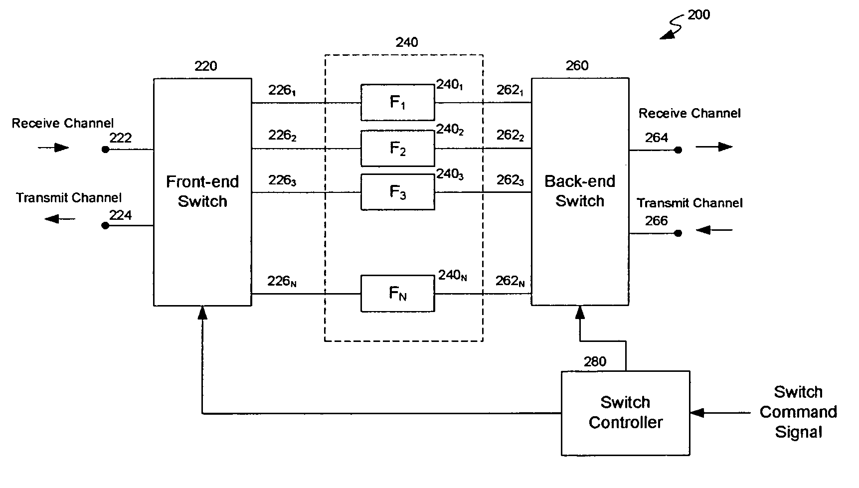
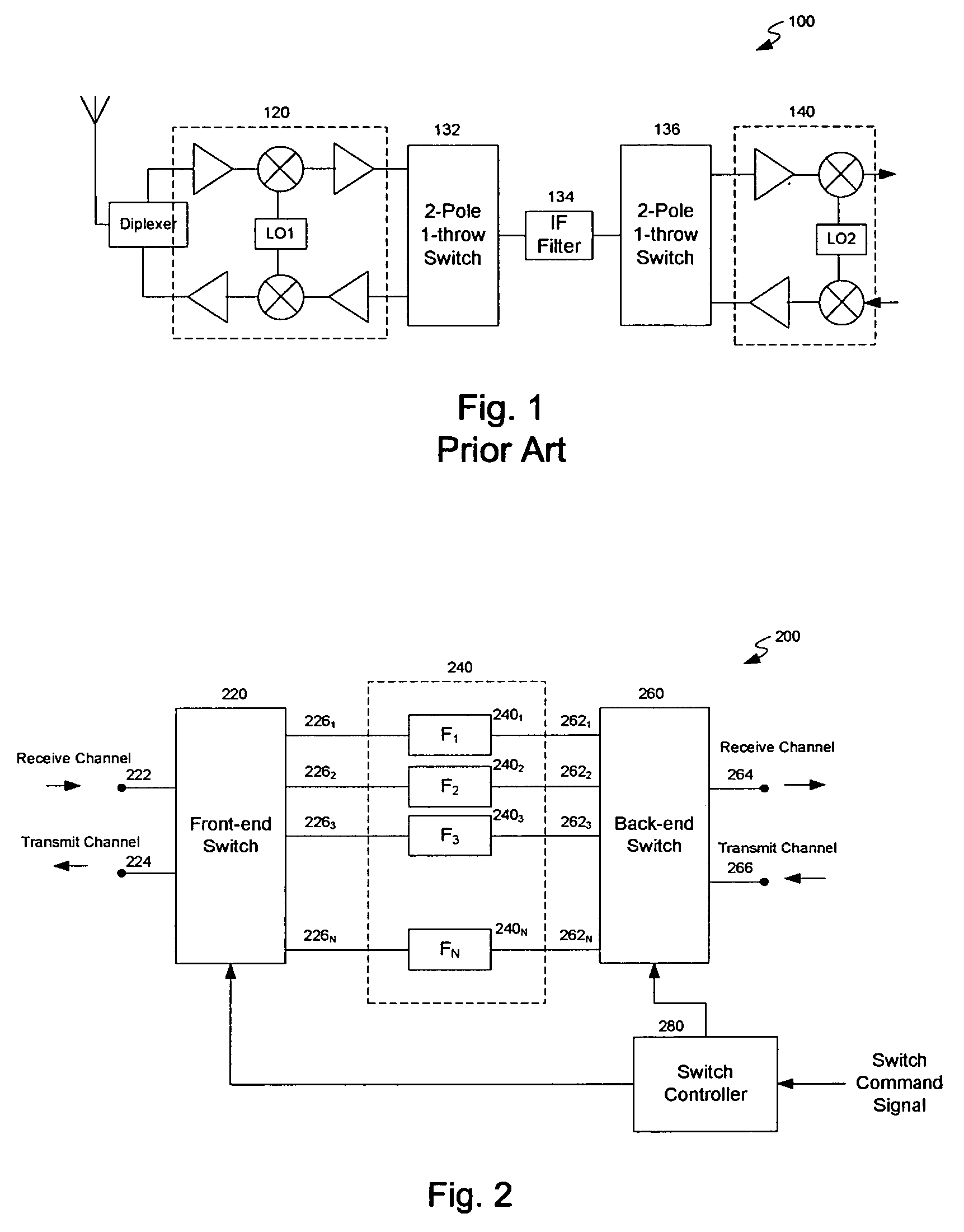
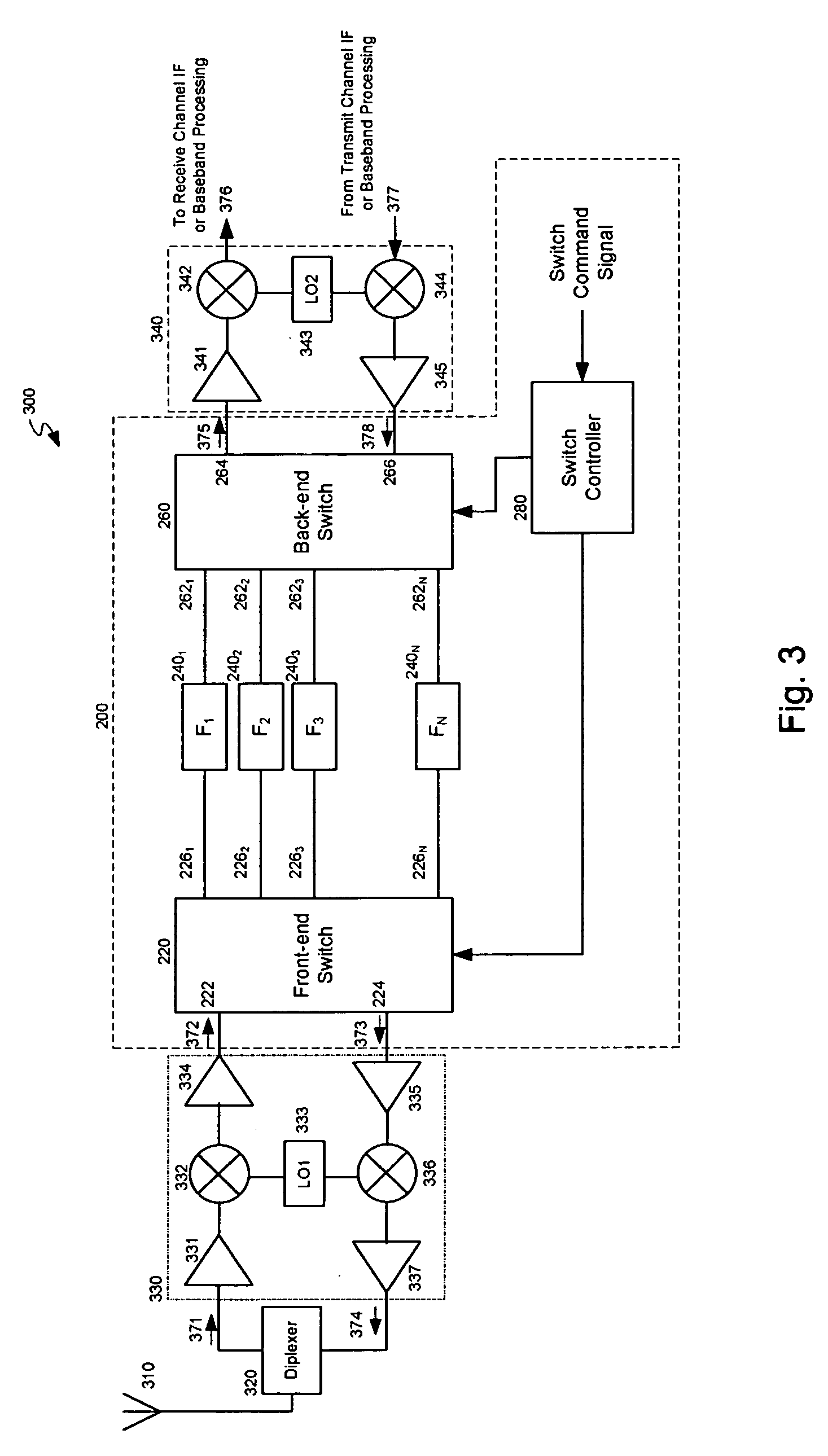
[0015]FIG. 2 illustrates a multi-channel filtering system in accordance with one embodiment of the present invention. The multi-channel filtering system 200 includes a front-end multi-pole, multi-throw switch 220 (“front-end switch” hereafter), filters F1-N 240, a back-end multi-pole, multi-throw switch 260 (“back-end switch” hereafter), and a switch controller 280. The multi-channel filtering system 200 is designed to intersect the transceiver's transmit and receive channels, thereby providing a range of available transmit and receive bandwidths, as described in greater detail below.

[0016]In the exemplary embodiment shown, the front-end switch 220 comprises two poles: a receive pole 222, and a transmit pole 224. The receive pole 222 is configured for coupling to front-end receiver circuitry and components, which may include frequency conversion stages, low noise or buffer amplifiers, limiter and similar components used in the receive channel. The transmit pole 224 is configured for...


PUM


Abstract

A multi-channel filtering system for use with a transceiver includes a front-end multi-pole, multi-throw switch, a back-end multi-pole, multi-throw switch, and a plurality of filters. The front-end switch includes a receive pole, a transmit pole, and a plurality of switch throws. The back-end switch also includes a receive pole, a transmit pole, and a plurality of switch throws. Each of the plurality of filters has first and second ports, each first port coupled to one of the switch throws of the front-end switch, and each second port coupled to one of the switch throws of the back-end switch. Using this configuration, filters of differing bandwidths can be switched in during signal reception and / or transmission, thereby tailoring the communication rate to the particular conditions.

Description

BACKGROUND[0001]The present invention relates generally to communication systems, and more specifically to multi-channel filtering systems and transceiver architectures having variable transmission and reception bandwidths.[0002]Present day communication systems are often limited in their reliability and speed by adjacent channel interference. Adjacent channel interference, or “spectral crowding” as it is referred to in wireless communication systems, occurs when one or more received signals occur adjacent to the intended signal, the adjacent signal's proximity and / or signal strength relative to the intended signal being such that the destination receiver is critically limited or unable to process the intended signal accurately. The problem often results in poor quality or dropped connections when a large number of users attempt to use the particular system's available bandwidth, as each user provides a potentially interfering signal to the other's intended signal. In addition, the ...

Claims


Application Information

Patent Timeline
Patent Type & Authority Patents(United States)
IPC IPC(8): H04B1/38H04B1/04H04B1/10H04B1/28H04B1/40H04B1/44
CPCH04B1/28H04B1/406
Inventor ROWE, DAVID A.HORNBUCKLE, CRAIG A.POPE, MATTHEW D
Owner SIERRA MONOLITHICS INC
Why Eureka
Try Eureka