Distributed wireless architecture using microcast

a wireless architecture and microcast technology, applied in the field of new architecture for cellular communication systems, can solve the problems of slow spillover of interference into neighboring cells, the power of any interfering signal diminishes with increasing distance between interfering users, etc., and achieves advantageous decoding and improved performance.

Inactive Publication Date: 2006-12-26
ERICSSON INC
View PDF38 Cites 30 Cited by
  • Summary
  • Abstract
  • Description
  • Claims
  • Application Information

AI Technical Summary

Benefits of technology

[0007]For digital transmissions, performance may be improved by delaying the modulation transmitted from one-third of the microstations in the active set for a given mobile terminal by one symbol period and advancing the modulation by one symbol period at another third of the microstations in the active set. A signal received at the mobile terminal thus appears to have propagated through a multipath channel with two symbol periods of time dispersion, and such a signal may be advantageously decoded using a Viterbi equalizer. The transmission timing may alternatively be adapted based on relative receive delays.

Problems solved by technology

In general, the power of any interfering signal diminishes with increasing distance between interfering users.
Unfortunately with this method of covering the service area, the spill-over of interference into neighboring cells diminishes only slowly with distance.

Method used


Image

  • Distributed wireless architecture using microcast
  • Distributed wireless architecture using microcast
  • Distributed wireless architecture using microcast

Examples


Embodiment Construction

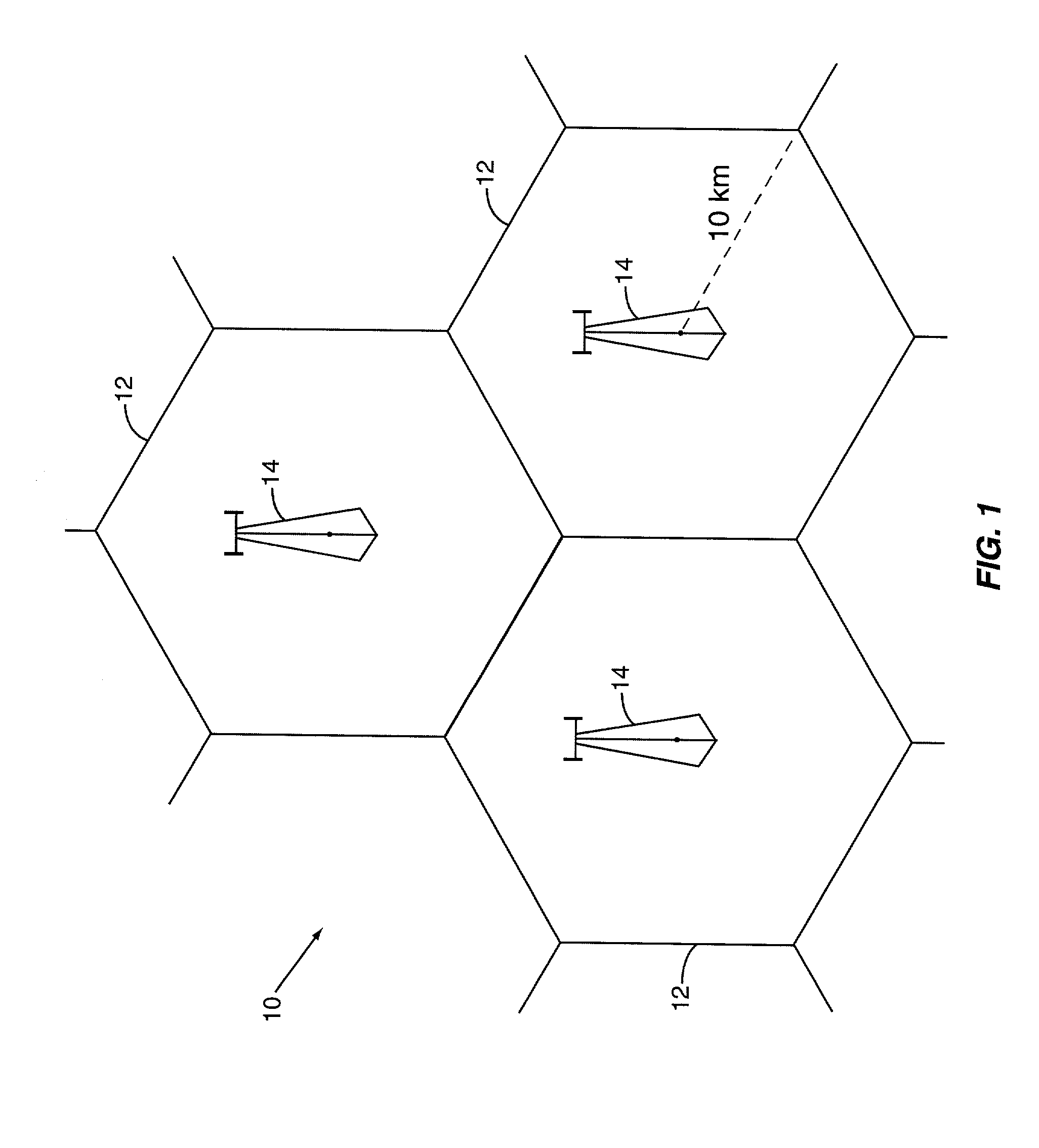
[0025]Referring now to the drawings, FIG. 1 illustrates a conventional macro-cellular communication system indicated generally by the numeral 10. The cellular communication system 10 comprises a plurality of relatively large cells 12 approximately 20 km in diameter. A centrally located base station 14 serves each cell 12. Signals transmitted by the base station 14 propagate from the base station 14 to the perimeter of the cell in all directions. The power of the signal transmitted from the base station 14 at any given point steadily diminishes as a function of the distance from the base station 14. In a vacuum, the signal strength varies inversely in proportion to the square of the distance from the base station 14. In practice, path loss in a cellular communication system is more severe than the inverse square law would predict due to terrain, atmospheric conditions, and other real-world effects. In general, it is normally assumed that the signal power at any given point varies inv...


PUM


Abstract

A mobile communication system comprises a plurality of cells, with each cell including a network of microstations distributed more or less uniformly throughout the cell. A central controller connected to the network of microstations selects a group of microstations in the vicinity of the mobile terminal to transmit information to the mobile terminal. The selected microstations in the active set for a given mobile terminal is continuously updated as the mobile terminal moves through the network of microstations to form a virtual cell that follows the mobile terminal through the network. Transmission conflicts between two mobile terminals is avoided by inhibiting transmissions from an active microstation to at least one of the co-channel mobile terminals when a transmission conflict is detected.

Description

BACKGROUND OF THE INVENTION[0001]The present invention relates to cellular communication systems and more particularly to a new architecture for a cellular communication system to reduce co-channel interference and increase system capacity.[0002]In cellular communication systems, frequency reuse plans allow the same frequency to be used more than once within the system. Thus in contrast with broadcasting, cellular systems divide a service region into smaller cells that transmit different signals for different users. The available frequencies are divided into frequency groups and each cell is assigned at least one frequency group to use for communications with mobile terminals within that cell.[0003]To avoid the problem of co-channel interference, cells assigned the same frequency group, known as co-channel cells, are spatially separated so that the mobile terminal operating within a cell receives the desired signal at a higher level than any potential interfering signal from co-chan...

Claims


Application Information

Patent Timeline
Patent Type & Authority Patents(United States)
IPC IPC(8): H04Q7/20H04B1/715H04J3/00H04W16/32H04W36/18
CPCH04B1/715H04W16/32H04B2001/7154H04W36/18H04W88/085
Inventor DENT, PAUL W.
Owner ERICSSON INC
Why Eureka
Try Eureka