Vibration damper with amplitude-selective damping force

a damping force and vibration technology, applied in the direction of shock absorbers, machine supports, other domestic objects, etc., can solve the problems of comparatively high cost of such sensors, and achieve the effects of high level of driving safety, and high degree of driving comfor

Inactive Publication Date: 2007-01-02
ZF FRIEDRICHSHAFEN AG
View PDF14 Cites 37 Cited by
  • Summary
  • Abstract
  • Description
  • Claims
  • Application Information

AI Technical Summary

Benefits of technology

[0006]The advantage consists in that amplitude-selective damping can now be used without restricting chassis response. Through a corresponding sensing of the driving situation, the amplitude-selective damping can be used to ensure a high degree of driving comfort on the one hand and a high level of driving safety on the other hand.
[0007]In another advantageous construction, the valve in the bypass can be controlled continuously. The damping force can therefore be deliberately adjusted in the operative range of the amplitude-selective damping.
[0008]According to a further innovation, at least one of the work spaces is connected to an adjustable damping valve. Various constructions of adjustable damping valves have already existed for a long time. In order to achieve a high degree of driving comfort also with high-frequency excitations, the response of the sensors for determining the driving situation must be correspondingly fast. However, sensors of this kind are comparatively expensive. Further, there is, in addition, the internal regulating time in the chassis system, so that the time for readjusting the damping force reaches its limits. By combining an adjustable damping valve with an amplitude-selective damping device, the high-frequency excitations are practically filtered out, so that longer overall regulating times with simpler sensors are permissible.

Problems solved by technology

However, sensors of this kind are comparatively expensive.

Method used


Image

  • Vibration damper with amplitude-selective damping force
  • Vibration damper with amplitude-selective damping force
  • Vibration damper with amplitude-selective damping force

Examples


Embodiment Construction

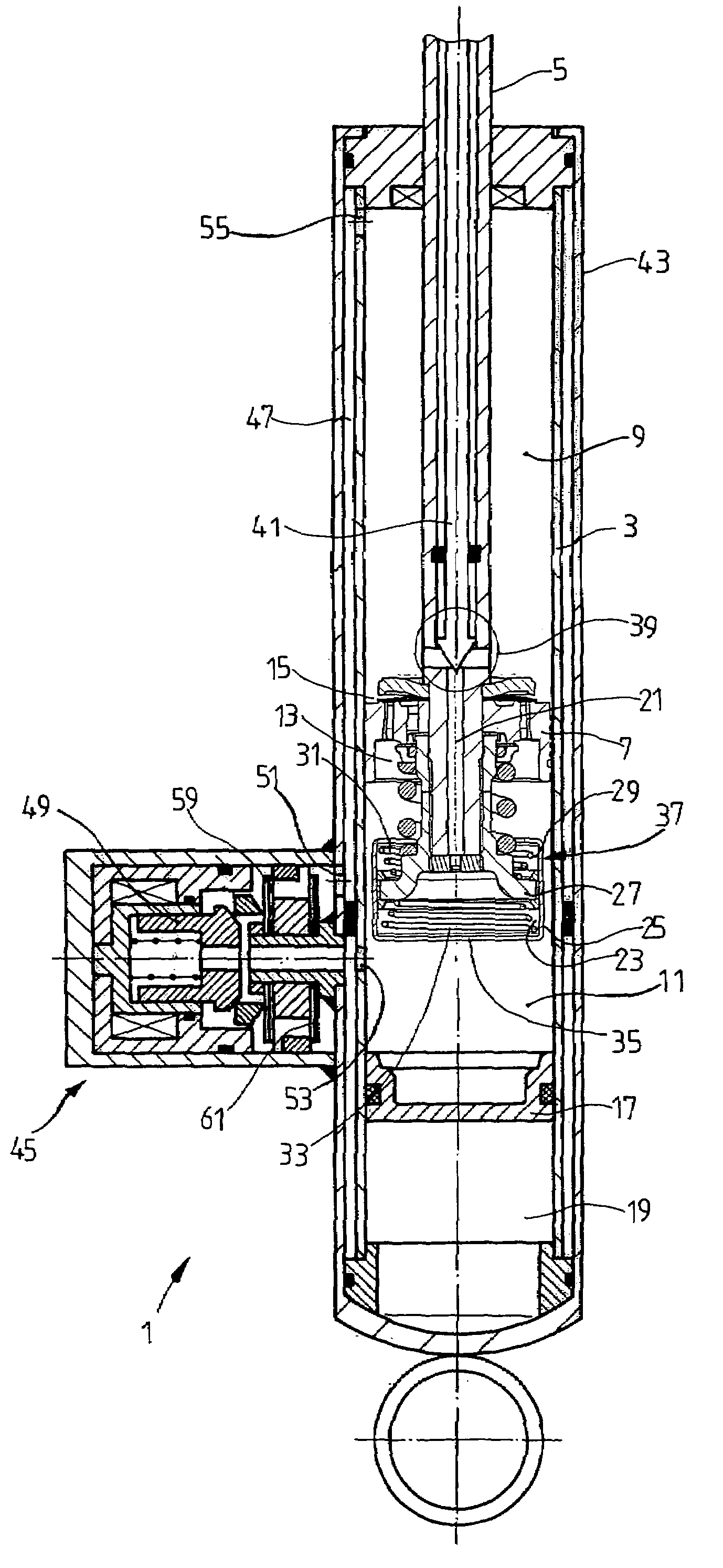
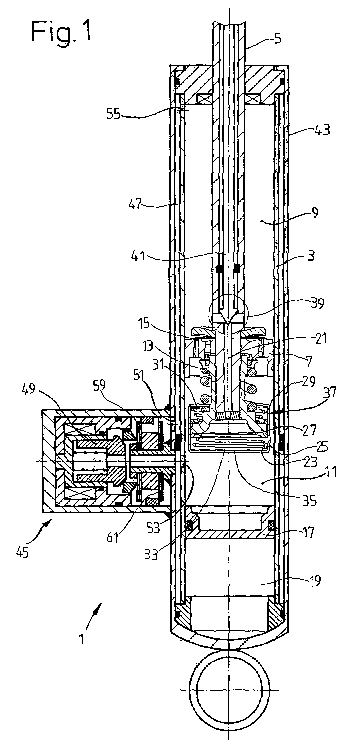
[0015]FIG. 1 shows a vibration damper 1. A piston rod 5 with a piston 7 is guided so as to be axially movable in the cylinder 3 of the vibration damper 1, this cylinder 3 being filled with damping medium. The piston divides the cylinder into a work space 9 on the piston rod side and a work space 11 remote of the piston rod. A damping valve 13, 15 is constructed in the piston for the rebound direction and for the compression direction, respectively. A separating piston 17 for a compensating space 19 filled with gas adjoins the work space remote of the piston rod.

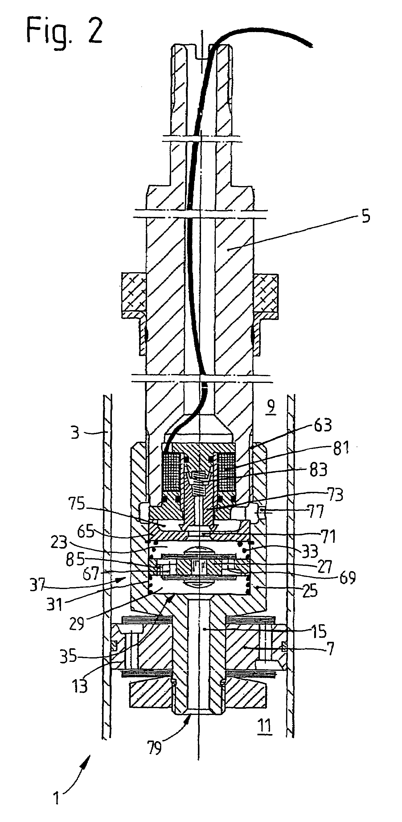
[0016]A bypass 21 is constructed inside the piston rod 5 proceeding from the work space 9 on the piston rod side and connects this work space 9 with a first work chamber 23 which is constructed in a housing 25 at the piston rod. The piston rod carries a separating piston 27 which separates the first work chamber from a second work chamber 29 in the housing 25. The housing 25 is supported by two springs 31; 33 at the separatin...


PUM


Abstract

Vibration damper includes a cylinder filled with a damping medium in which a piston rod with a piston is guided in an axially movable manner, wherein the piston divides the cylinder into a work space on the piston rod side and a work space remote of the piston rod. A bypass connects at least one of the two work spaces with a first work chamber in a housing in which an axially movable separating piston separates the first work chamber from a second work chamber, the bypass being controlled by a switchable valve.

Description

BACKGROUND OF THE INVENTION[0001]1. Field of the Invention[0002]The invention is directed to a vibration damper with amplitude-selective damping force including a cylinder filled with damping medium; a piston rod guided in the cylinder in an axially movable manner, the piston rod carrying a piston which divides the cylinder into a work space on the piston rod side and a work space remote from the piston rod; and a housing which is axially movable in one of the work spaces, the housing containing an axially movable separating piston which separates the housing into a first work chamber and a second work chamber.[0003]2. Description of the Related Art[0004]In vibration dampers operating in an amplitude-selective manner such as are known, for example, from U.S. Pat. No. 6,220,409, DE 40 02 882 C1, U.S. Pat. No. 6,352,145 and EP 1 152 166 A1, at least one work space of the vibration damper is connected to a housing in which a separating piston is displaceable axially within limits betwe...

Claims


Application Information

Patent Timeline
Patent Type & Authority Patents(United States)
IPC IPC(8): F16F9/44F16F9/46F16F9/508F16F9/512
CPCF16F9/5126F16F9/466
Inventor PRADEL, ROBERTBAALMANN, HELMUT
Owner ZF FRIEDRICHSHAFEN AG
Why Eureka
Try Eureka