Strip continuous supply apparatus and method

a continuous supply and continuous supply technology, applied in the direction of chemistry apparatus and processes, thin material processing, lamination ancillary operations, etc., can solve the problems of inability to precisely set the splicing standby position and the diameter of the new web roll cannot be determined accurately

Active Publication Date: 2007-01-02
KOMORI CORP
View PDF10 Cites 11 Cited by
  • Summary
  • Abstract
  • Description
  • Claims
  • Application Information

AI Technical Summary

Benefits of technology

[0009]The present invention has been accomplished in light of the above-mentioned problems. It is the object of the invention to provide a strip continuous supply apparatus and method which can not only determine the diameter of a new web roll accurately regardless of the shape of a turret arm, but also set the new web roll at a splicing standby position precisely, by measuring the distance from a position opposed to the circumferential surface of the new web roll to the circumferential surface of the new web roll when the new web roll stops at a diameter measuring position.
[0028]According to the present invention with the above-described features, when the new web roll stops at the diameter measuring position, the distance from the position opposed to the circumferential surface of the new web roll to the circumferential surface of the new web roll is measured. Based on the measured value, the diameter of the new web roll can be determined, and the turret arm drive device is controlled, whereby the new web roll can be set at the splicing standby position. Thus, it becomes possible to splice a web roll having a diameter smaller than the external dimension of the turret arm, so that high precision splicing control can be exercised.

Problems solved by technology

Thus, there are problems that the diameter of the new web roll cannot be determined accurately, and the new web roll cannot be set precisely at the splicing standby position.

Method used


Image

  • Strip continuous supply apparatus and method
  • Strip continuous supply apparatus and method
  • Strip continuous supply apparatus and method

Examples


embodiment

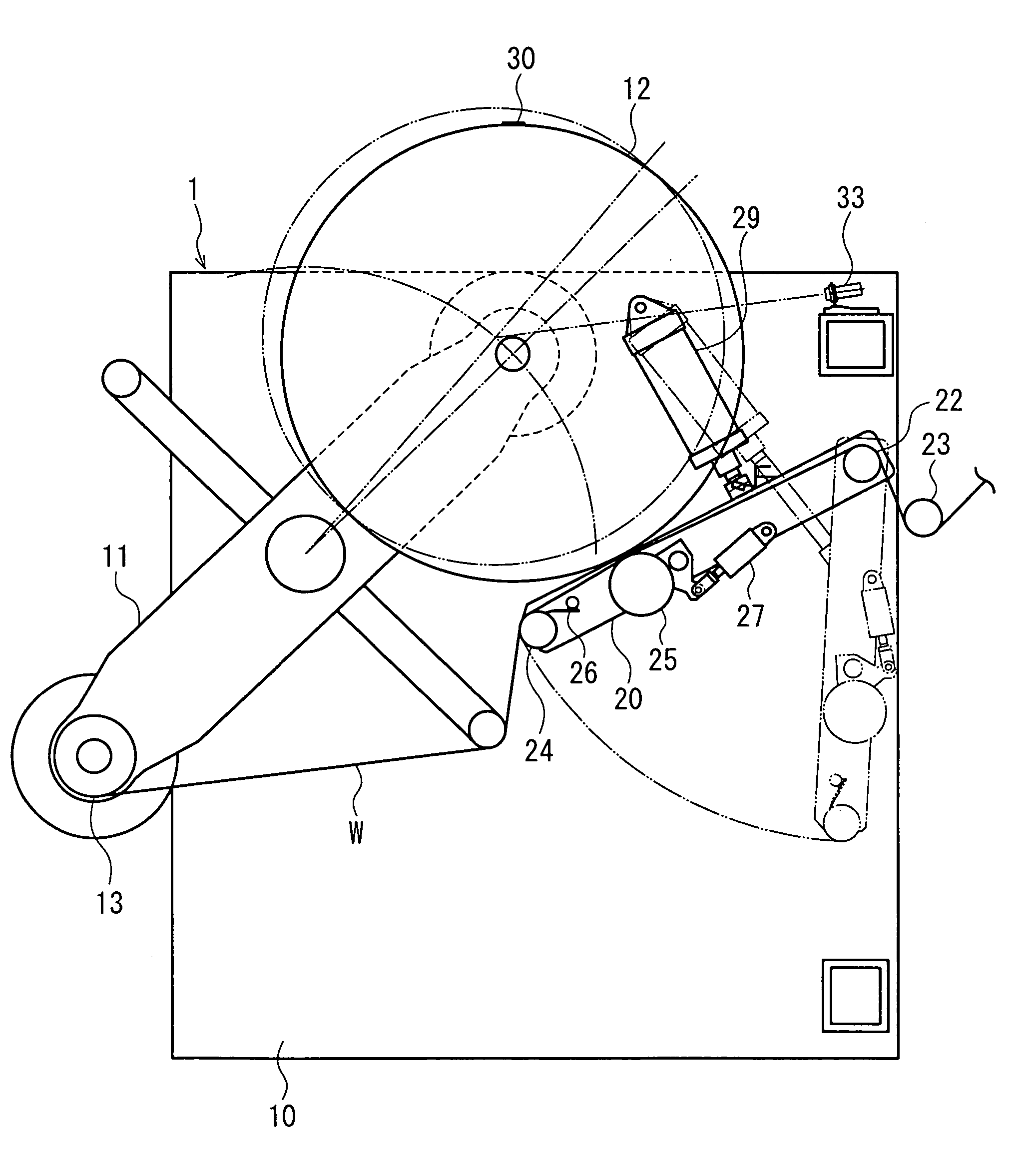
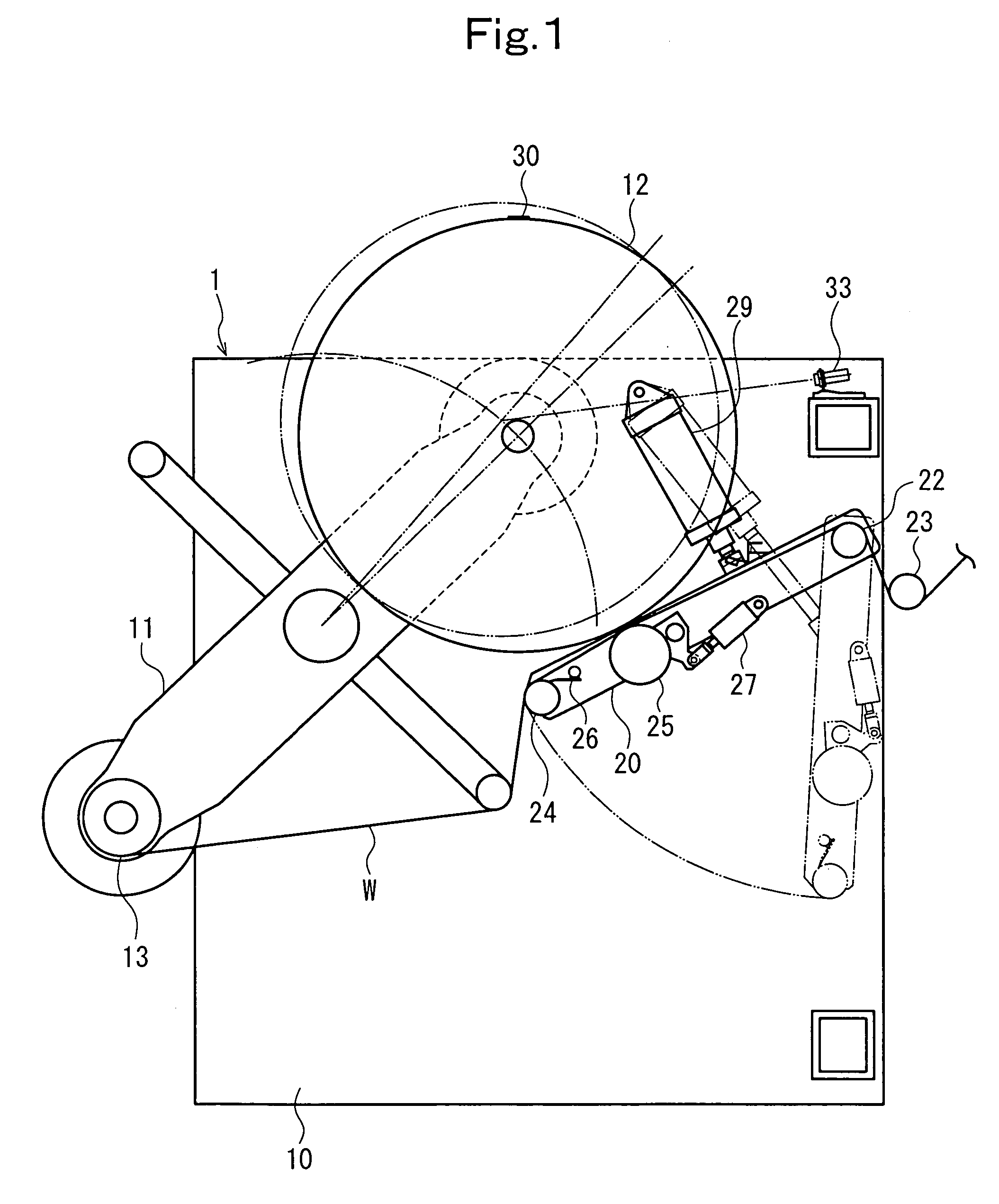
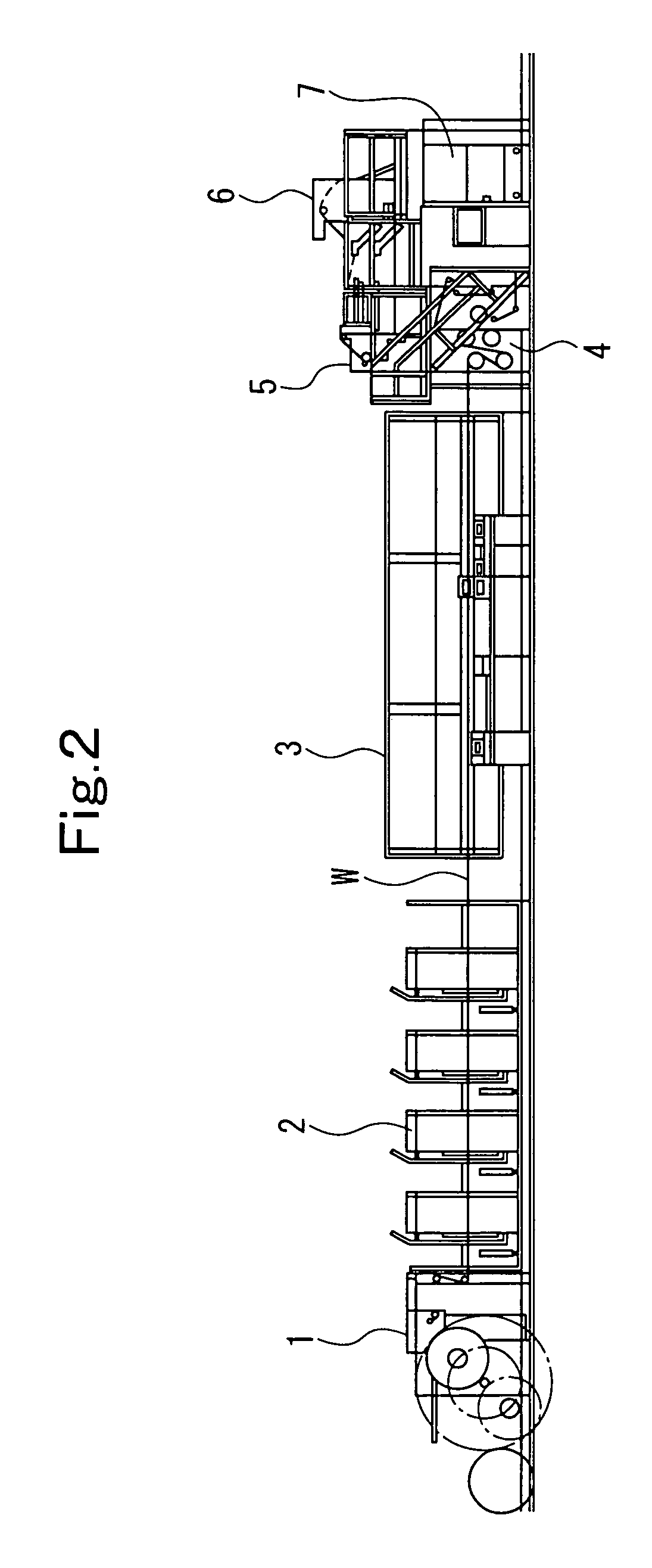
[0037]FIG. 1 is a schematic configurational drawing of a feeding apparatus (strip continuous supply apparatus) showing an embodiment of the present invention. FIG. 2 is an external view of an offset rotary press. FIG. 3 is a control block diagram. FIGS. 4 to 6 are flowcharts for splicing control.

[0038]In an offset rotary press, as shown in FIG. 2, a web (strip) W, continuously supplied from a feeding apparatus (strip continuous supply apparatus) 1, undergoes various printings while passing through printing units 2. Then, the web W is heated and dried when passed through a dryer 3. Then, the web W is cooled when passed through a cooling device 4. Then, when passing through a web path device 5 and a drag device 6, the web W is subjected to tension control or a change in direction. Then, the web W is cut to a predetermined shape and folded by a folder 7.

[0039]In the feeding apparatus 1, as shown in FIG. 1, a turret arm 11 has a central portion journaled by an apparatus body 10. A new w...


PUM


Abstract

A feeding apparatus comprises a rotatably supported turret arm for supporting a new web roll and an old web roll, and a turret arm turning motor for rotating the turret arm, and splices a web of the new web roll to a web of the old web roll, thereby continuously supplying a web. The feeding apparatus further comprises a web roll diameter measuring distance meter, provided at a position opposed to the circumferential surface of the new web roll when the new web roll stops at a diameter measuring position, for measuring the distance to the new web roll; and a control device for determining the diameter of the new web roll in accordance with an output from the distance meter, and driving the turret arm turning motor in accordance with the determined diameter of the new web roll to move the new web roll to a splicing standby position.

Description

CROSS REFERENCE TO RELATED APPLICATION[0001]The entire disclosure of Japanese Patent Application No. 2003-335235 filed on Sep. 26, 2003, including specification, claims, drawings and summary, is incorporated herein by reference in its entirety.BACKGROUND OF THE INVENTION[0002]1. Field of the Invention[0003]This invention relates to a strip continuous supply apparatus and method preferred for application to a feeding apparatus or the like of a rotary press.[0004]2. Description of the Related Art[0005]In a machine, for example, a rotary press, that uses a roll (a web in wound form) while unwinding it, an operation is continued by automatically splicing a roll being unwound (i.e., an old web roll) to a new roll (a new web roll) by use of an automatic splicing apparatus, without stopping the operation of the machine, when the old web roll approaches the end of its unwinding (see Japanese Patent Application Laid-Open No. 2002-308485).[0006]Conventionally, a diameter measuring device for ...

Claims


Application Information

Patent Timeline
Patent Type & Authority Patents(United States)
IPC IPC(8): B65H19/18B65H21/00B65H19/12B65H26/08
CPCB65H19/1868B65H19/1821B65H2553/51B65H2513/11B32B38/18B32B41/00
Inventor SHIRAISHI, YOSHIHIDENOGUCHI, KAZUSHI
Owner KOMORI CORP
Why Eureka
Try Eureka