Internal diameter measuring method for transparent tube

a technology of transparent tubes and measuring methods, applied in the direction of measuring devices, instruments, using optical means, etc., can solve problems such as unavoidable errors, and achieve the effect of accurate measurement, avoiding fluctuations, and reducing errors

Active Publication Date: 2018-08-28
MITUTOYO CORP
View PDF11 Cites 4 Cited by
  • Summary
  • Abstract
  • Description
  • Claims
  • Application Information

AI Technical Summary

Benefits of technology

[0018]The present invention provides an internal diameter measuring method for a transparent tube which can measure an internal diameter of the transparent tube accurately using a parallel laser light beam.
[0019]Inventors arrived at the present invention based on the knowledge that an outer diameter measurement of a cylindrical object has, on each of two sides, one intersection between a threshold value and a detection signal of a light amount, and in contrast, an internal diameter measurement of a transparent tube has two intersections between a peak of the detection signal corresponding to the internal diameter and the threshold value on each of two sides of the peak. In the present invention, by detecting a position intersecting with the threshold value at two points on each side and by obtaining a position of a midpoint thereof, a position of a light beam corresponding to an inner circumferential surface is measured accurately, and therefore, the internal diameter can be measured accurately. Specifically, the present invention includes the following configuration.
[0021]In the present invention, a center position of the peak can be detected by taking the average value of the two intersection points where the peak of the detection signal formed by the light beam reflected by the inner circumferential surface of the transparent tube intersects the threshold value. The center position corresponds to the center position of the light beam reflected by the inner circumferential surface of the transparent tube and thus corresponds accurately to the position of the inner circumferential surface of the transparent tube. Therefore, the internal diameter can be found accurately by calculating positions on two sides of the inner circumferential surface based on the center position. Furthermore, according to the present invention, even when the positions of the intersection points of the detection signal fluctuate because the threshold value fluctuates, effects from fluctuation can be avoided by detecting the position of the midpoint and the internal diameter can be found accurately based on this point.
[0022]In the measuring method of the present invention, preferably, the calculation of the width direction positions of the inner circumferential surface is performed on two sides of the transparent tube and the internal diameter of the transparent tube is calculated from the width direction positions of the inner circumferential surface on the two sides. In the present invention, the internal diameter can be measured accurately since the internal diameter is calculated from positions on two sides of the inner circumferential surface. In addition, when the center position of the transparent tube is accurately found, the inner diameter can be measured even from the position on a single side of the inner circumferential surface. However, by measuring each position on the two sides of the transparent tube, the internal diameter can be measured accurately.
[0023]According to the present invention, the internal diameter of the transparent tube can be measured accurately using the parallel laser light beam.

Problems solved by technology

Because of this, errors are unavoidable when detecting the positions (P5 and P6) exceeding the threshold value T.

Method used


Image

  • Internal diameter measuring method for transparent tube
  • Internal diameter measuring method for transparent tube
  • Internal diameter measuring method for transparent tube

Examples


Embodiment Construction

[0031]The particulars shown herein are by way of example and for purposes of illustrative discussion of the embodiments of the present invention only and are presented in the cause of providing what is believed to be the most useful and readily understood description of the principles and conceptual aspects of the present invention. In this regard, no attempt is made to show structural details of the present invention in more detail than is necessary for the fundamental understanding of the present invention, the description taken with the drawings making apparent to those skilled in the art how the forms of the present invention may be embodied in practice.

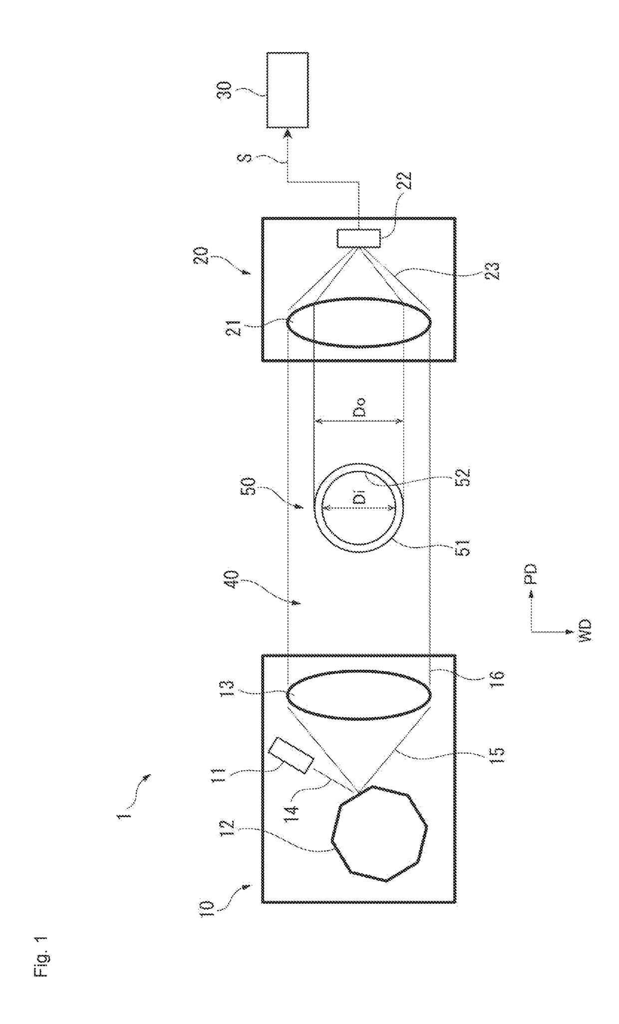
[0032]Hereafter, an embodiment of the present invention is described based on FIGS. 1 to 3. In FIG. 1, a measuring apparatus 1 is a device measuring an outer dimension of a measured object (a transparent tube 50) using a parallel laser light beam. In the present embodiment, a laser scanning micrometer is used for the measuring ap...


PUM


Abstract

A transparent tube is placed in a parallel laser light beam emitted from a light projector and reaching a photoreciever, and a detection signal indicating an amount of light received corresponding to a width direction position of the parallel laser light beam is obtained from the photoreceiver. Peaks formed in the detection signal by beams reflected by an inner circumferential surface of the transparent tube and incident to the photoreceiver are detected; width direction positions of two intersection points where the peaks cross a predetermined threshold value are detected; the width direction positions of the light beam reflected by the inner circumferential surface of the transparent tube are calculated from an average value of the two intersection points; and an internal diameter of the transparent tube is measured from the width direction positions.

Description

CROSS-REFERENCE TO RELATED APPLICATIONS[0001]The present application claims priority under 35 U.S.C. § 119 of Japanese Application No. 2015-244245, filed on Dec. 15, 2015, the disclosure of which is expressly incorporated by reference herein in its entirety.BACKGROUND OF THE INVENTION[0002]1. Field of the Invention[0003]The present invention relates to an internal diameter measuring method for a transparent tube.[0004]2. Description of Related Art[0005]Optical measuring apparatuses are used in order to conduct non-contact measurement of an external dimension of a measured object (such as an outer diameter of a cylindrical object). For example, a laser scan micrometer, image sensor micrometer, or light-section type 2D (two dimensional) shape measuring sensor is used. These apparatuses detect the outer diameter and the like of the measured object from measurements of shaded sections blocked by the measured object, using a plurality of parallel laser light beams arranged in a band shap...

Claims


Application Information

Patent Timeline
Patent Type & Authority Patents(United States)
IPC IPC(8): G01B11/02G01B11/12G01B11/24
CPCG01B11/2433G01B11/12
Inventor IMAIZUMI, RYOICHI
Owner MITUTOYO CORP
Why Eureka
Try Eureka