Adjustable tie down mechanism for roof rack and interior rail systems

a technology of interior rail system and adjustable mechanism, which is applied in the direction of flexible elements, packaging, cargo supporting/securing components, etc., can solve the problem of difficult removal complex mechanism of typical thumb wheel system

Inactive Publication Date: 2007-01-02
SPORTRACK
View PDF5 Cites 30 Cited by
  • Summary
  • Abstract
  • Description
  • Claims
  • Application Information

AI Technical Summary

Benefits of technology

[0007]The present invention includes an adjustable tie-down mechanism made up of a rail and a tie-down assembly. The rail is in the basic shape of a “C” channel. Slots or in the alternative, detents, are located in the channel to allow the tie-down assembly to be inserted into a prescribed location. The tie-down assembly includes several components: a lock plate, a tie-down assembly loop, a sliding block, and a pin for fastening the lock plate to the tie-down assembly loop. The lock plate is used to secure the tie-down assembly to the rail. The tie-down loop is inserted into the sliding block with at least one compressed spring disposed between the sliding block base and tie-down loop. It is contemplated by this invention that the spring may be disposed around the pin or proximate the pin. The spring provides a biasing force so that the lock plate positively secures the tie-down assembly to the rail. By pressing the tie-down loop in a direction opposite to the biasing force of the spring, the lock plate can be released so that the tie-down assembly can be slid to another detent position on the rail. In one embodiment of the invention, pressing the tie-down loop and turning it approximately ninety (90) degrees releases the tie-down loop from the rail. The tie-down assembly can then be easily removed from the rail.

Problems solved by technology

In addition, the typical thumb wheel system is a complex mechanism that is difficult to remove once the tie-down assembly is locked into position.

Method used


Image

  • Adjustable tie down mechanism for roof rack and interior rail systems
  • Adjustable tie down mechanism for roof rack and interior rail systems
  • Adjustable tie down mechanism for roof rack and interior rail systems

Examples


Embodiment Construction

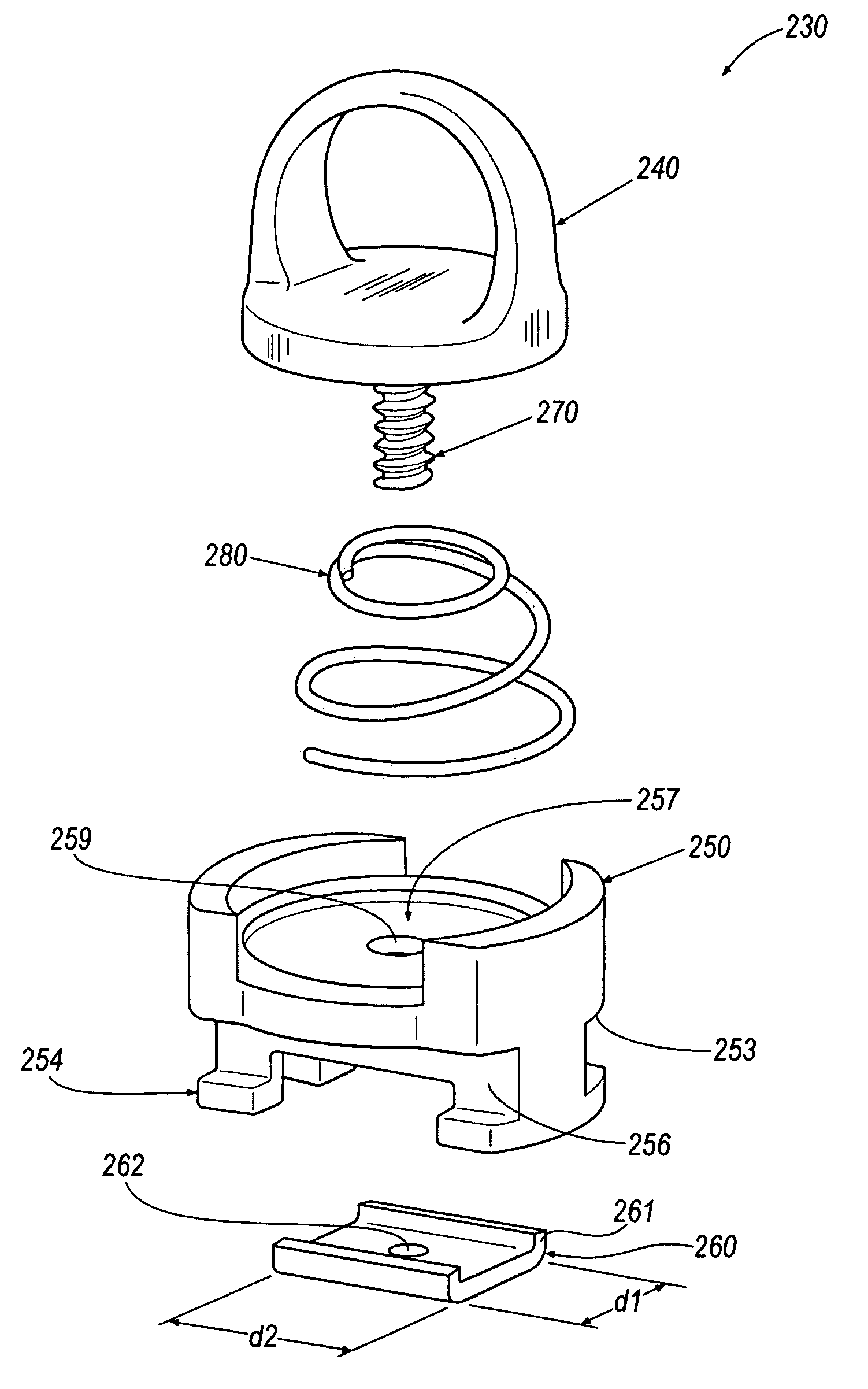
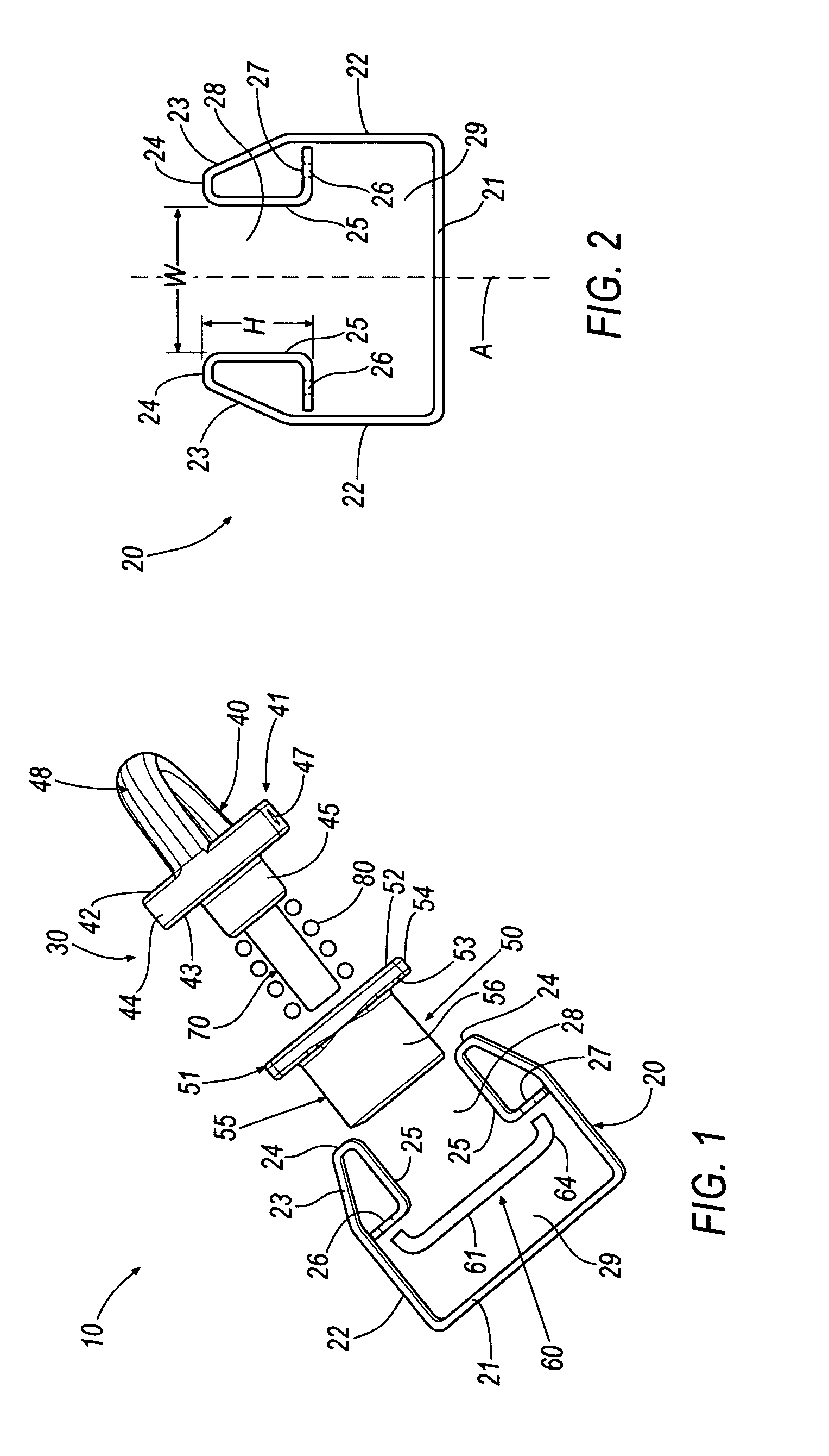
[0037]FIGS. 1 to 19 illustrate one embodiment of an adjustable tie-down mechanism, shown generally at 10, described herein. The tie-down mechanism 10 includes a rail, shown generally at 20, and a tie-down assembly, shown generally at 30. The rail 20 is one form of a securing member and other means for securing the tie-down mechanism 10 are contemplated by the embodiments described herein.

[0038]As seen in FIGS. 1 and 2, the rail 20 includes a generally planar base 21 for mounting the rail 20 to a structure, such as a vehicle, by any suitable means such as through the use of a bolt passing through an aperture formed through base 21 for securement to the structure (not shown). Each of a pair of outer side walls 22 extends generally perpendicularly from the base 21. Thus, the outer side walls 22 are substantially parallel to each other, so that the rail has a “C” cross-sectional shape, as best shown in FIG. 2.

[0039]Each of a pair of outer side walls 22 includes an angled portion 23, eac...


PUM


Abstract

An adjustable tie-down assembly includes a pin having a first end and a second end. A lock plate is disposed proximate the second end and a sliding block is partially received within an opening of a rail. The block is adapted to receive the pin. A tie-down loop is disposed proximate the first end and at least one spring member is disposed proximate the sliding block. The spring member is adapted to bias the tie-down loop in a first direction away from the sliding block and the spring member is adapted to secure the lock plate to the rail.

Description

CROSS-REFERENCE TO RELATED APPLICATIONS[0001]The present continuation-in-part application claims priority from the utility patent application (Ser. No. 10 / 825,456) filed on Apr. 15, 2004, and the U.S. provisional application (Ser. No. 60 / 463,291) filed Apr. 16, 2003, the entire contents of which are herein incorporated by reference.FIELD OF THE INVENTION[0002]The present invention relates to a tie-down system, and in particular to an adjustable tie-down mechanism for a vehicle's roof rack or interior rail system having a simplified structure that can be easily installed, positioned, or removed without the need for tools.BACKGROUND[0003]With the growing popularity of sport utility vehicles (SUVs), minivans, station wagons, and trucks, the need for a tie-down system as an internal or external application has also grown in popularity. The most common type of tie-down system used in the automotive field for roof racks or article carriers includes a thumb-wheel mechanism to secure a tie-...

Claims


Application Information

Patent Timeline
Patent Type & Authority Patents(United States)
IPC IPC(8): B61D45/00
CPCB61D45/001B60P7/0815
Inventor SAWARD, RONALD G.HARBERTS, JOHN H.KLINKMAN, JOHN EDWARD
Owner SPORTRACK
Why Eureka
Try Eureka