Catalytic converter and catalyst element therefor

Active Publication Date: 2007-01-02
MIRATECH GRP
View PDF12 Cites 35 Cited by
  • Summary
  • Abstract
  • Description
  • Claims
  • Application Information

AI Technical Summary

Benefits of technology

[0006]The present invention provides an improved catalytic converter assembly and catalyst element therefor which satisfy the needs and alleviate the problems mentioned above. The improvements provided by the present invention are very low cost and are extremely effective for preventing exhaust gas from bypassing the catalyst element(s). The inventive modifications are also helpful for facilitating the insertion and removal of the catalyst elements from the converter housing.
[0007]In one aspect, the present invention provides an improvement to a catalytic converter wherein the catalytic converter includes: a housing having a longitudinal flow passage; at least one catalyst element removably positionable in the housing across the longitudinal flow passage; an insertion channel projecting from the housing for insertion of the catalyst element; and a cover removably positionable on the outer end of the insertion channel. In accordance with the present invention, the improvement comprises a solid extension secured on the catalyst element such that, when the catalyst element is positioned in the housing, the solid extension will project into the insertion channel in a manner effective to at least partially block flow around the catalyst element.
[0008]In another aspect, the present invention provides an improvement for a catalyst element wherein the catalyst element is positionable in a catalytic converter housing across a longitudinal flow passage and the catalyst element is removably insertable in the housing via an insertion channel projecting from the housing. In accordance with the present invention, the improvement comprises a solid extension secured on the catalyst element such that, when the catalyst element is positioned in the catalytic converter housing, the solid extension will project into the insertion channel in a manner effective to at least partially block flow around the catalyst element.

Problems solved by technology

Unfortunately, a common problem with the catalytic converter assemblies heretofore used in the art is that it has been difficult to achieve and maintain an adequate seal around the perimeter of the catalyst element(s) 4.
In this regard, it has been particularly difficult to adequately ensure that exhaust gas does not bypass the catalyst element(s) 4 by flowing into the insertion channel 6 and over the top of the element(s) 4.
However, the use of a padding or mat material of this type has not been sufficiently effective or reliable.

Method used


Image

  • Catalytic converter and catalyst element therefor
  • Catalytic converter and catalyst element therefor
  • Catalytic converter and catalyst element therefor

Examples


embodiment 15

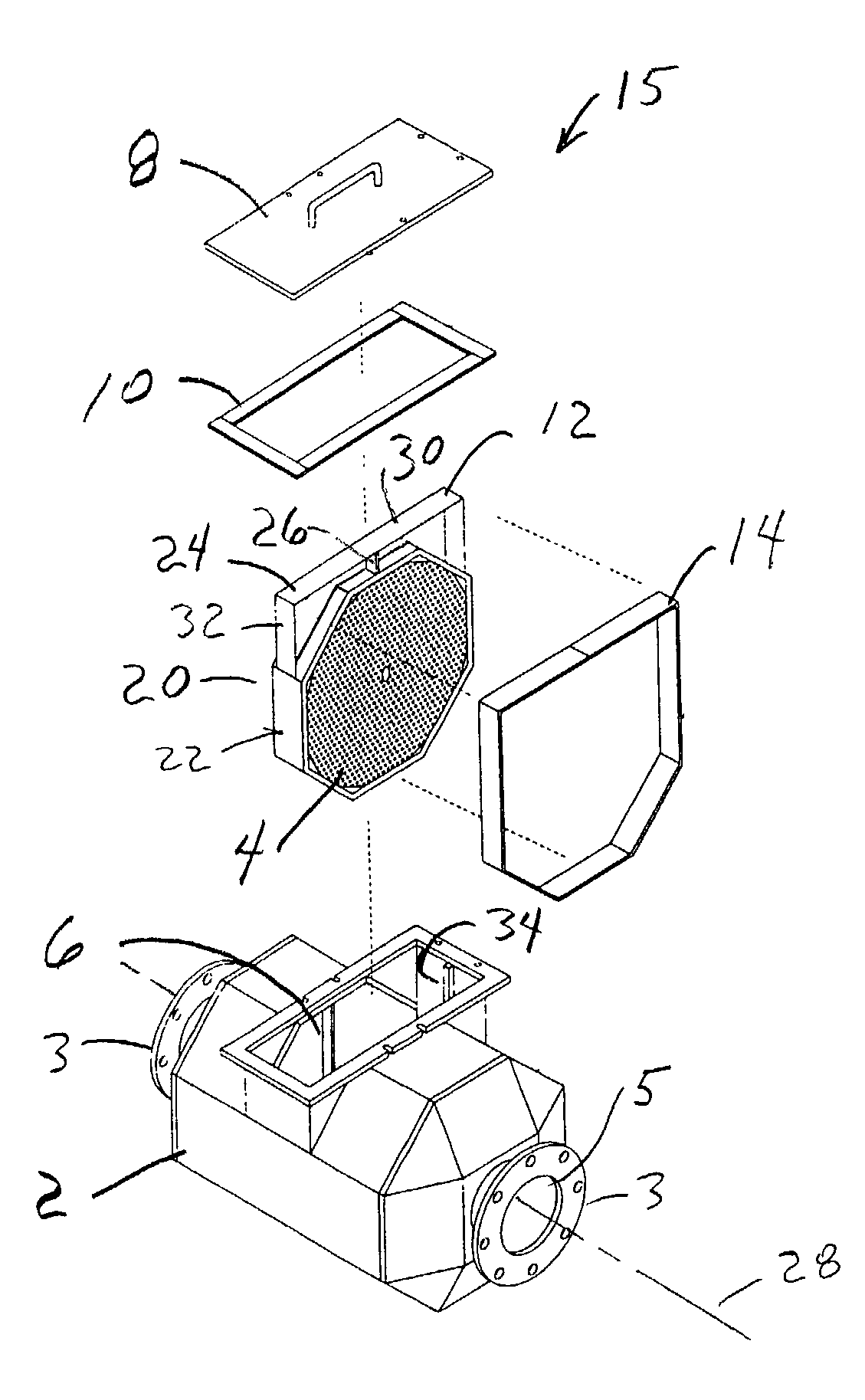
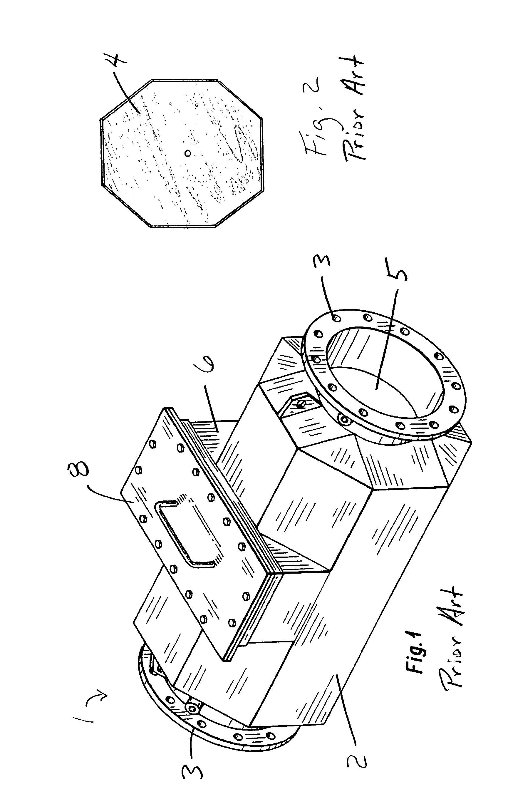
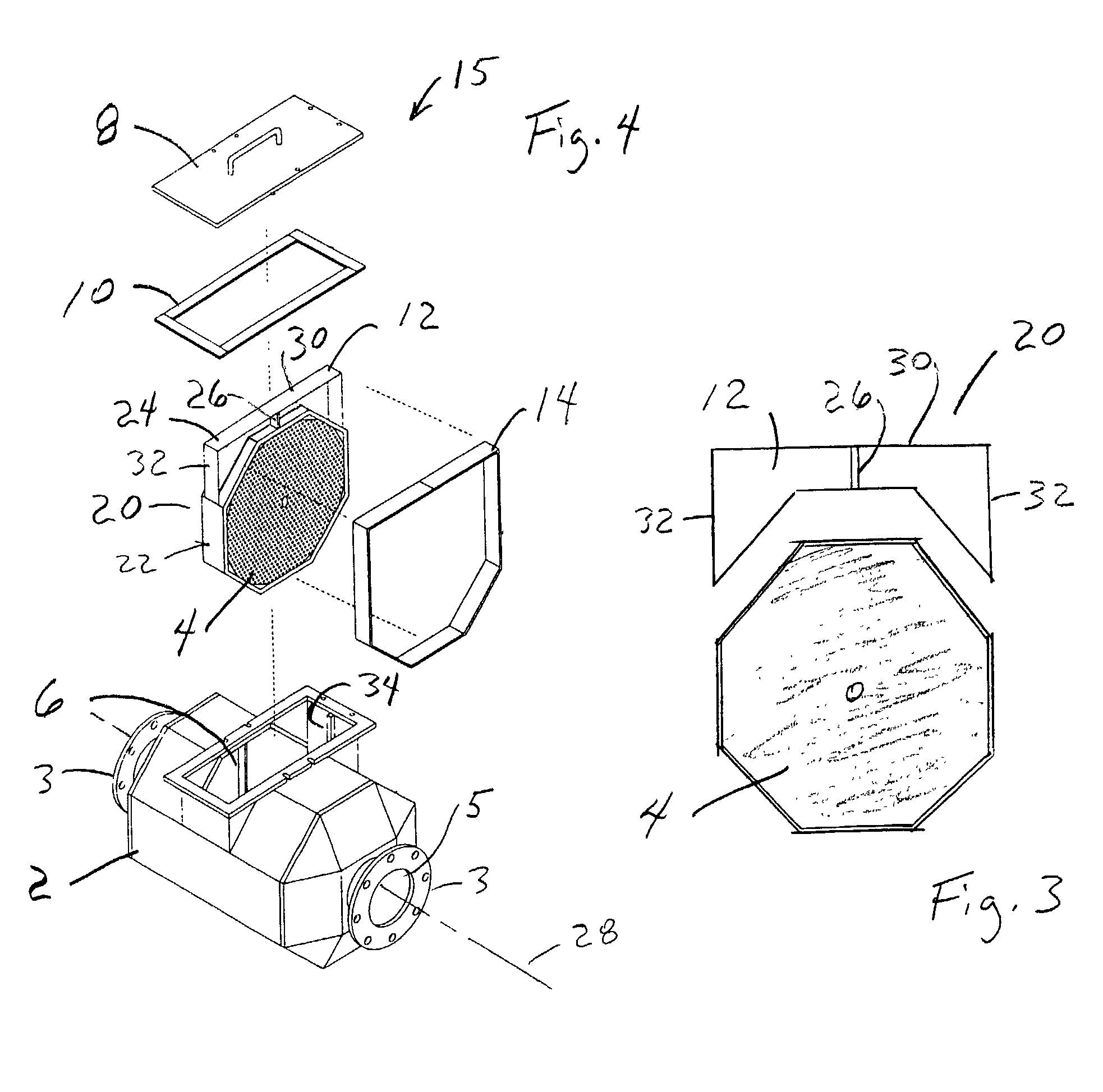
[0016]An embodiment 15 of the inventive catalytic converter assembly is depicted in FIG. 4. As with the prior art assembly 1, the inventive converter assembly 15 comprises: a housing 2 having end flanges or other connection elements 3; an exhaust gas flow passage 5 extending longitudinally through housing 2; a catalyst element insertion channel 6 projecting from and extending laterally across housing 2; a cover 8 removably positionable on the outer end of insertion channel 6; and a cover gasket 10 positioned on the outer rim of insertion channel 6 for sealing against the cover 8.

[0017]An inventive catalyst element 20 which is particularly well suited for use in inventive converter assembly 15 is depicted in FIGS. 3, 4, and 5. The inventive catalyst element 20 preferably comprises a catalyst element 4 of the type described above for use in prior art converter assembly 1 and a solid extension 12 attached to (e.g., by welding or other suitable means) and projecting radially from the up...

embodiment 40

[0021]Although the inventive catalytic converter assembly 15 depicted in FIG. 4 utilizes an octagonal catalyst element 4, it will be understood that the housing of the inventive converter assembly can be configured to utilize circular catalyst elements, oval catalyst elements, or other catalyst elements having generally any desired shape. An alternative embodiment 40 of the inventive catalyst element comprising an inventive solid extension 42 secured to and projecting radially from a round catalyst element 44 is depicted in FIG. 6.


PUM

PropertyMeasurementUnit
Flow rateaaaaaaaaaa
Shapeaaaaaaaaaa

Abstract

An industrial catalytic converter and a removable catalyst element therefor wherein a solid extension is secured on the catalyst element such that, when the catalyst element is positioned in the converter housing, the solid extension will project into the element insertion channel of the housing in a manner effective to at least partially block the flow of exhaust gas around the catalyst element.

Description

FIELD OF THE INVENTION[0001]The present invention relates to catalytic converters and catalyst elements therefor. More particularly, but not by way of limitation, the present invention relates to catalytic converters, and catalyst elements therefor, for use with industrial engines.BACKGROUND OF THE INVENTION[0002]Emissions control systems for industrial engines, particularly large, stationary, reciprocating engines, commonly include catalytic converters having removable catalyst elements. The use of removable elements allows periodic inspection, cleaning, and replacement of the catalyst elements without removing or replacing the catalytic converter housing.[0003]A catalytic converter assembly 1 of the type heretofore used in the art, as well as a removable catalyst element 4 therefor, are depicted in FIGS. 1 and 2. The catalytic converter assembly 1 comprises: a housing 2 wherein one or more (typically a plurality) of the catalyst elements 4 are removably received; a pair of flanges...

Claims


Application Information

Patent Timeline
IPC IPC(8): B01D50/00
CPCB01D53/9454F01N3/2803F01N13/0097F01N3/2839F01N2450/30Y02T10/22Y02T10/12
Inventor NEWBURRY, DONALD M.
Owner MIRATECH GRP
Why Eureka
Try Eureka