
Coaxial cables having improved smoke performance

a technology of coaxial cables and smoke performance, which is applied in the direction of power cables, cables, insulated conductors, etc., can solve the problem that the plenum area may present a particular hazard

Active Publication Date: 2007-01-02
COMMSCOPE INC
View PDF18 Cites 19 Cited by
  • Summary
  • Abstract
  • Description
  • Claims
  • Application Information

AI Technical Summary

Benefits of technology

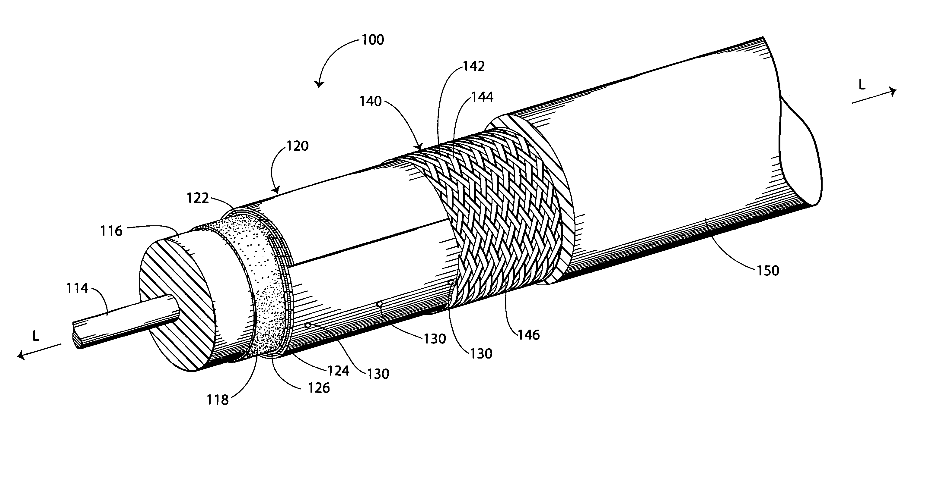
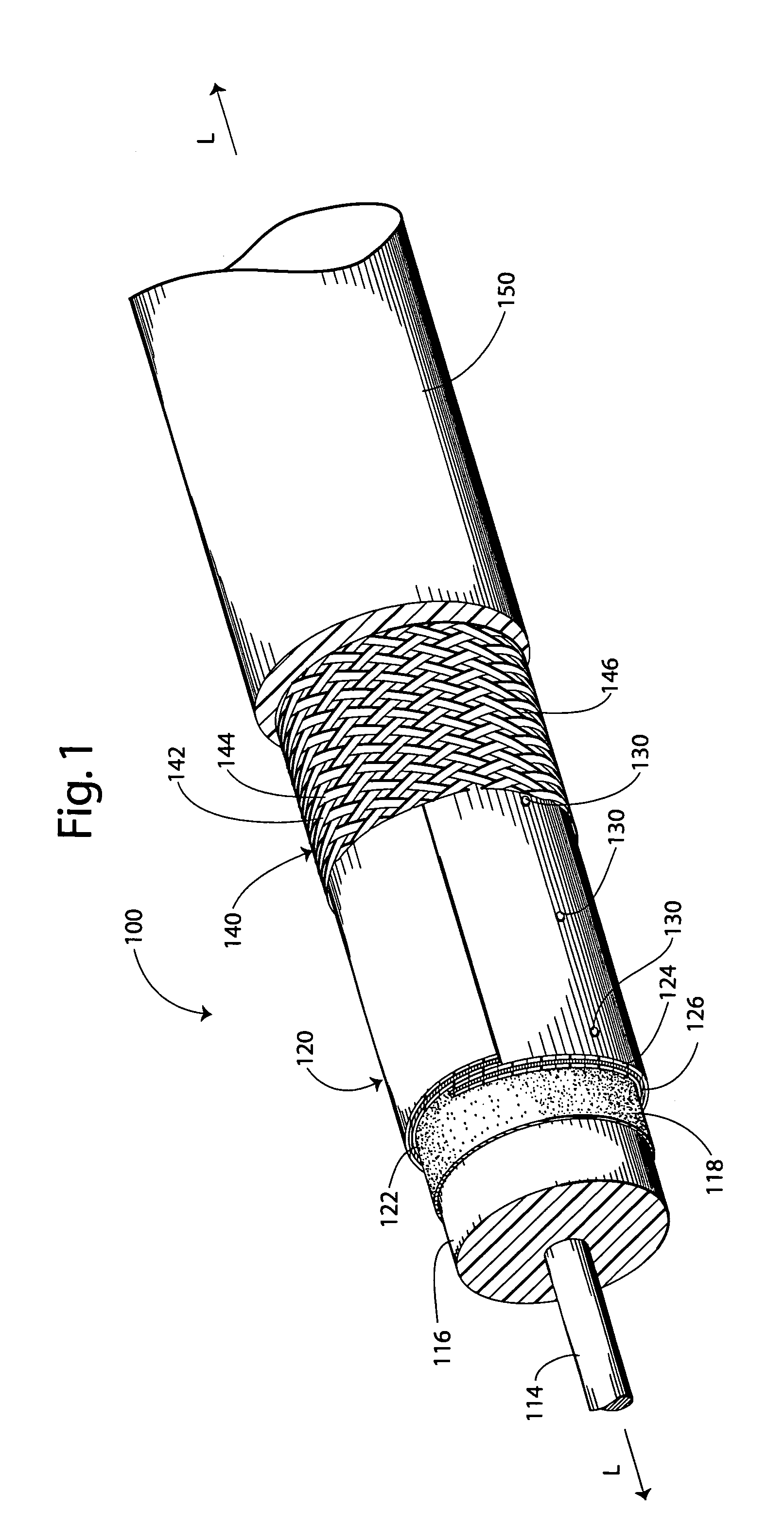
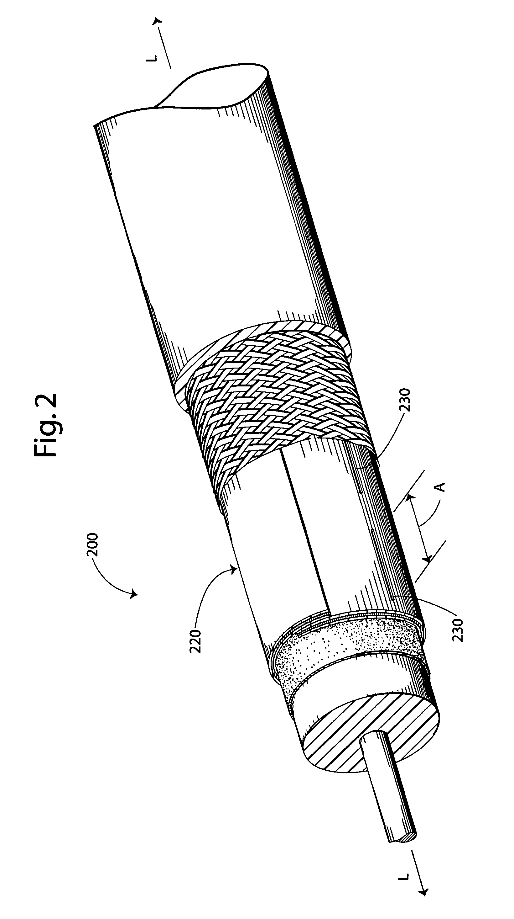
The present invention provides a coaxial cable design that allows for the flow of at least a portion of the melted dielectric layer and any smoke or gas that may be generated during a fire through the perforations in the outer conductor and into the voids in the second outer conductor. This design ensures that the shielding effectiveness of the cable is not degraded by more than about 7 dB as compared to a cable without the perforations. The cable is also designed to pass NFPA (2002) and to allow for the flow of at least a portion of the melted dielectric layer and any smoke or gas that may be generated during a fire through the perforations in the outer conductor and into the voids in the second outer conductor.

Problems solved by technology

Plenum areas may present a particular hazard in the event of a fire because there are few barriers to contain flame and smoke within the plenum.

Method used


Image

  • Coaxial cables having improved smoke performance
  • Coaxial cables having improved smoke performance
  • Coaxial cables having improved smoke performance

Examples


Embodiment Construction

[0010]The present invention now is described more fully hereinafter with reference to the accompanying drawings, in which embodiments of the invention are shown. This invention may, however, be embodied in many different forms and should not be construed as limited to the embodiments set forth herein; rather, these embodiments are provided so that this disclosure will be thorough and complete, and will fully convey the scope of the invention to those skilled in the art.

[0011]Like numbers refer to like elements throughout. In the figures, the thickness of certain lines, layers, components, elements or features may be exaggerated for clarity. Broken lines illustrate optional features or operations unless specified otherwise.

[0012]The terminology used herein is for the purpose of describing particular embodiments only and is not intended to be limiting of the invention. As used herein, the singular forms “a”, “an” and “the” are intended to include the plural forms as well, unless the c...


PUM

PropertyMeasurementUnit
thicknessaaaaaaaaaa
thicknessaaaaaaaaaa
shielding effectivenessaaaaaaaaaa

Abstract

A coaxial cable includes an elongate inner conductor. A dielectric layer surrounds the inner conductor. A first outer conductor surrounds the dielectric layer and has perforations defined therein. A second outer conductor surrounds the first outer conductor. A polymeric jacket surrounds the second outer conductor. The cable is adapted such that, when the dielectric layer is melted, at least a portion thereof and / or smoke therefrom can flow through the perforations in the first outer conductor. According to some embodiments, the second outer conductor defines a plurality of voids therein and, when the dielectric layer is melted, at least a portion thereof and / or smoke therefrom can flow through the perforations in the first outer conductor and into the voids. According to some embodiments, the second outer conductor is braided.

Description

FIELD OF THE INVENTION[0001]The present invention relates to coaxial cables and, more particularly, to coaxial cables having improved smoke performance.BACKGROUND OF THE INVENTION[0002]Coaxial cables are commonly employed as plenum cables. A plenum cable is a cable that is run in the plenum space of a building. The plenum space is a space that is used for air circulation in heating and air conditioning systems, for example, and is typically located between a structural ceiling and a suspended ceiling or under a raised floor. Plenum cables may be used for transmitting video, telephone, and / or data signals through a building, for example. Plenum areas may present a particular hazard in the event of a fire because there are few barriers to contain flame and smoke within the plenum. Therefore, plenum cables may be subject to safety standards such as National Fire Protection Agency NFPA 262 Standard Method for Flame Travel and Smoke of Wires and Cables for Use in Air Handling Spaces (200...

Claims


Application Information

Patent Timeline
Patent Type & Authority Patents(United States)
IPC IPC(8): H01B7/18
CPCH01B11/1826
Inventor HUFFMAN, JASON
Owner COMMSCOPE INC
Learn More