Oscillating-type generator

a generator and oscillating technology, applied in the direction of generator/motor, current collector, rotary current collector, etc., can solve the problem of how efficiently the number of impacting actions can be increased, and achieve the effect of efficient generation of electricity

Inactive Publication Date: 2007-01-02
USC
View PDF9 Cites 28 Cited by
  • Summary
  • Abstract
  • Description
  • Claims
  • Application Information

AI Technical Summary

Benefits of technology

[0014]With this means, by reducing the period of oscillation of the generator member, the number of times that the impact member strikes the piezoelectric elements per unit time is increased. To reduce the period requires reducing the mass of the generator member and increasing the spring constant. Increasing the spring constant, however, consumes a large amount of energy in a short duration and thus requires the external force to be increased. When the external force contemplated is not large enough, an appropriate spring constant is selected that allows the generator member to be oscillated by that force and still makes the oscillation period as small as possible.
[0038]With this means, because the housings are arranged to cross each other, when subjected to vibrations in a plurality of directions, the impact member in at least one of the housings impacts the piezoelectric elements to generate electricity. Further, since the impact member and the piezoelectric elements are combined as a set and accommodated in each of the housings that are assembled in a crossing configuration, the impact members do not interfere with each other during oscillation, thus efficiently generating electricity.

Problems solved by technology

Hence, in producing a greater amount of electricity as a whole, the problem that needs to be addressed is how efficiently the number of impacting actions can be increased.

Method used


Image

  • Oscillating-type generator
  • Oscillating-type generator
  • Oscillating-type generator

Examples


embodiment 1

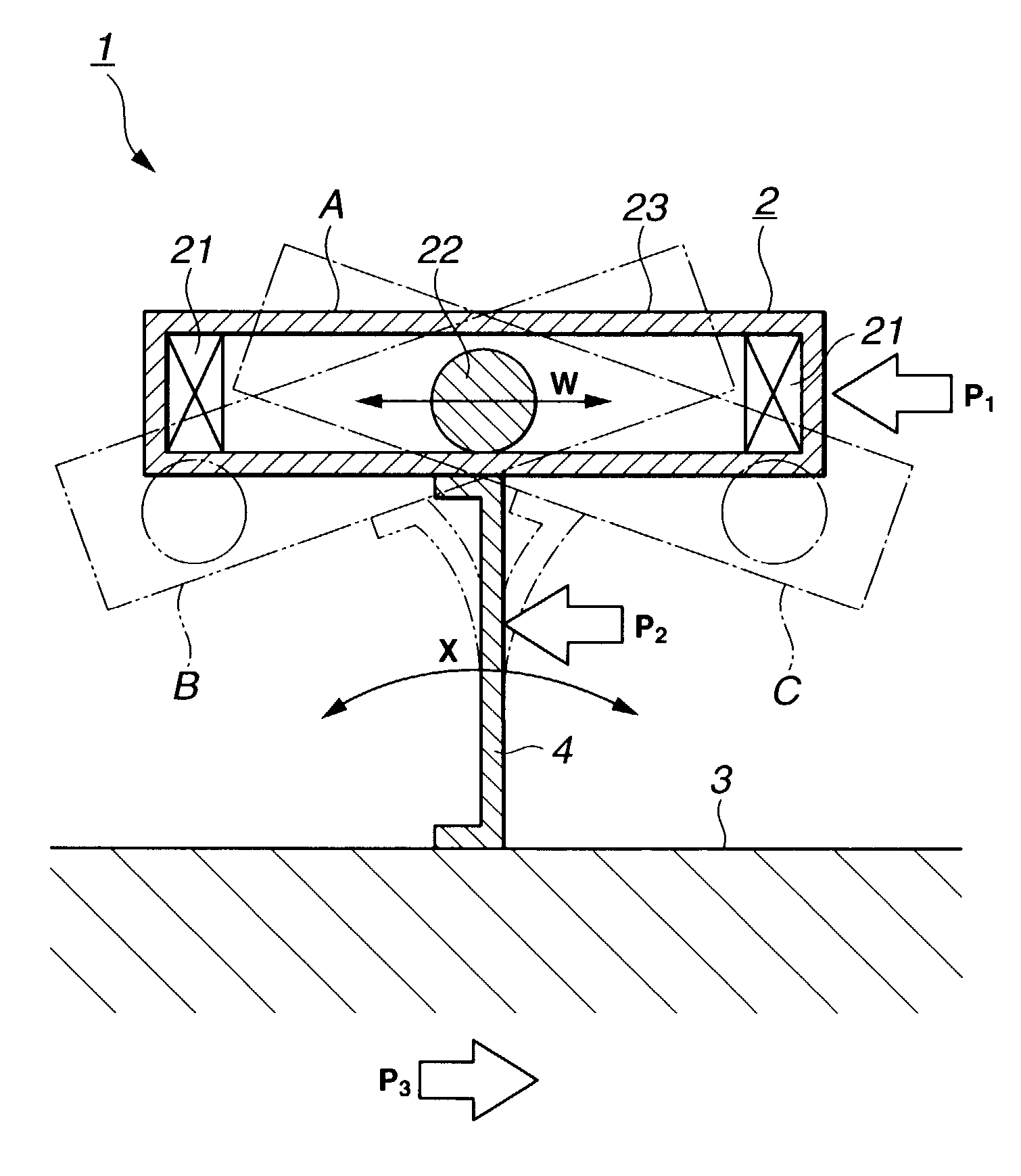
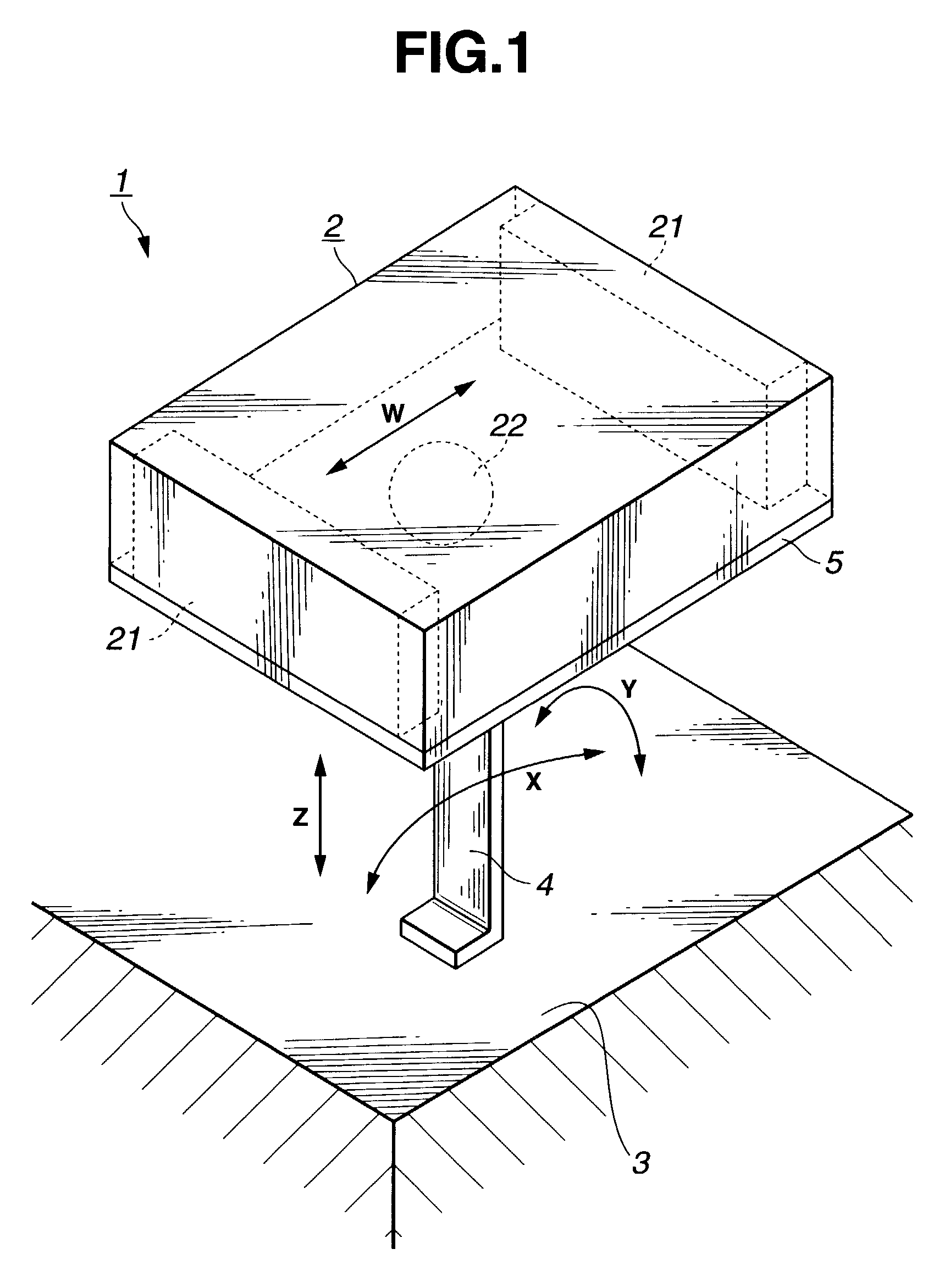
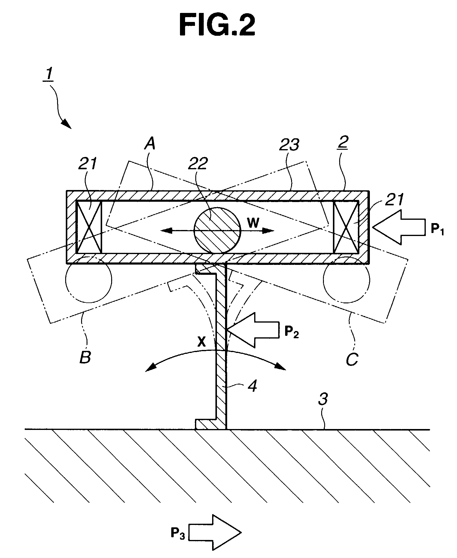
[0061]The spring constant of the elastic member 4 in the impact direction is selected to match an applied external force to make the period of oscillation of the generator member 2 as small as possible. By reducing the oscillation cycle of the generator member 2, the number of impacts made by the impact member 22 against the piezoelectric element 21 per unit time can be increased, which in turn increases the amount of electricity produced as a whole. To reduce the cycle requires reducing a mass of the generator member and increasing the spring constant. Increasing the spring constant, however, consumes a large amount of energy in a short duration and thus requires the external force to be increased. The magnitude of the external force differs according to the environment in which the oscillating-type generator 1 is installed. Thus, considering an expected magnitude of the external force, an appropriate spring constant is selected that allows the generator member to be oscillated or ...

embodiment 2

[0075]With this arrangement the elastic member 4 of the embodiment 2 can cause the generator member 2 to oscillate efficiently, increasing the number of impacts of the impact member per unit time and the amount of electricity generated. As for the rubber and gel materials, by changing the length, width and height, the spring constant can easily be provided with a desired directivity or the value of the spring constant changed.

[0076]Further, as shown in FIG. 6, the elastic member 4 may be divided into a plurality of pieces (two in this example) in connecting the generator member 2 and the base member 3. In this case also, these elastic members 4 are all mounted so that the X direction in which the spring constant is smallest agrees with the impact direction (W direction). The construction of FIG. 6 may be applied to the embodiment 1.

[0077]Next, an embodiment 3 of this invention will be described by referring to the accompanying drawings. FIG. 7 is an external perspective view of the ...

embodiment 3

[0078]The embodiment 3 is a variation of the previous embodiment 1 and 2 in terms of how the elastic member 4 is mounted. As the elastic member 4 a leaf spring is used in this embodiment. As shown in FIG. 7 and FIG. 8, the elastic member 4 made from an elongate, thin, platelike elastic body is curved and fixed to the base member 3, with the generator member 2 secured to a curved apex portion of the elastic member 4 through a narrow surface contact. The generator member 2 is mounted in such a way that the impact direction of the generator member 2 (W direction) aligns with a line connecting the ends of the elastic member 4. With the elastic member 4 curved in this manner and moved in the most easily displaceable direction (X direction), the impact member 22 can be struck against the piezoelectric elements 21. The elastic member 4 may be formed from rubber or gel materials shaped like a thin plate, instead of the leaf spring. In this embodiment too, the elastic member 4 utilizes the b...


PUM


Abstract

An oscillating-type generator is provided in which an impact member impacts piezoelectric elements to generate electricity and which can efficiently increase the number of impacts and generate a large amount of electricity. This oscillating-type generator includes: a generator member 2 having an impact member 22 impacting piezoelectric elements 21 to generate electricity; and an elastic member 4 having elasticity, attached to the generator member 2 and, when applied an external force, adapted to oscillate the generator member 2 to cause the impact member 22 to repeat impacting the piezoelectric elements 21.

Description

BACKGROUND OF THE INVENTION[0001]1. Field of the Invention[0002]The present invention relates to a technical field of a generator using a piezoelectric element.[0003]2. Description of the Prior Art[0004]A technology has been proposed which utilizes a piezoelectric effect, by which a mechanical energy of a piezoelectric material is transformed into an electrical energy, and incorporates a piece of the piezoelectric material into a small device for use in generators. A variety of materials have been known, both inorganic and organic, which exhibit the piezoelectric effect. Of these, lead zirconium titanate (PZT)-based ceramic materials have attracted attention as a viable piezoelectric element and made a significant progress toward practical use.[0005]For example, Japanese Patent Laid-Open No. 2001-145375 proposes a generator using piezoelectric elements. This official gazette discloses a structure in which two opposing piezoelectric elements are arranged in a container with an impact...

Claims


Application Information

Patent Timeline
Patent Type & Authority Patents(United States)
IPC IPC(8): H01L41/08H02N2/00H01L41/113H02N2/18
CPCH02N2/183
Inventor SAKAI, YASUHIRO
Owner USC
Why Eureka
Try Eureka