Programmable asynchronous pipeline arrays

a pipeline array and pipeline technology, applied in the field of pipelined asynchronous logic circuits, can solve the problems of clocked systems suffering from a number of inherent drawbacks, requiring global retiming of the entire system, and adding high-speed retiming hardware support to a clocked fpga, and achieves high token throughput.

Active Publication Date: 2007-01-02
CORNELL RES FOUNDATION INC +1
View PDF7 Cites 114 Cited by
  • Summary
  • Abstract
  • Description
  • Claims
  • Application Information

AI Technical Summary

Benefits of technology

[0008]The present invention addresses the foregoing need through provision of a high-performance pipelined asynchronous logic gate array architecture that is suitable for use in FPGAs and other programmable asynchronous systems. The architecture is based on the use of very fine-grain pipelines in which each pipeline stage contains only a small amount of logic (e.g., a 1-bit full-adder) and combines computation with data latching, such that explicit output latches are absent from the pipeline. More particularly, each pipeline stage used in the preferred embodiments is characterized by the fact that the stage employs a data channel for its inputs and handshaking to control data flow in and out of the stage. This pipeline style achieves high data throughput and can also be used to design energy-efficient systems.
[0010]In the first preferred embodiment, the logic block includes five notable components that efficiently implement asynchronous computations. These include a group of input buffers for input pipelining and routing, a function unit that can implement any function of four variables, a conditional unit for conditionally sending or receiving message tokens, an output copy stage for copying and routing result tokens generated by the function or conditional units, and a state unit for feeding the function unit output back to its input for initialization.
[0013]The output copy pipeline stage is used to copy result tokens from the logic block and statically route them to the output ports of the logic block. The function unit and conditional unit can both source tokens to the output copy pipeline stage. Additionally, the input buffers can also source tokens to the output copy, which allows the logic block to support low-latency copy processes that bypass the function and conditional units.
[0016]Ease of pipelining: enables high-throughput logic cores that are easily composable and reusable, where asynchronous handshakes between pipeline stages enforce correctness (not circuit delays or pipeline depths as in clocked circuits).

Problems solved by technology

These clocked systems suffer from a number of inherent drawbacks.
Changing local pipeline depths in a clocked system can require global retiming of the entire system since the delays imposed by the pipeline vary with its depth.
Adding high-speed retiming hardware support to a clocked FPGA incurs a significant register overhead.
In addition, clocked FPGAs are prone to delay variation induced errors that can result from temperature and supply voltage fluctuations, as well as from physical imperfections of the circuit chip, for example.
Further, clocked FPGAs are not efficient from an energy usage standpoint because all of the logic gates in the array are enabled by each clock pulse, even when many of the gates are not required for a given computation.
However, while the first FPGA was introduced by Xilinx in 1985 and the first asynchronous microprocessor was designed at Caltech in 1989, very little work has been performed in the last two decades to combine asynchronous and programmable circuit technology.
Moreover, what work has been done in this area has not been particularly successful and has been based largely on programmable clocked circuits.
These FPGAs are limited to low-throughput logic applications because their asynchronous pipeline stages are either built up from gate-level programmable cells or use bundled-data pipelines.
Another drawback of previously proposed asynchronous FPGAs is that they could not use generic synchronous FPGA place and route tools.

Method used


Image

  • Programmable asynchronous pipeline arrays
  • Programmable asynchronous pipeline arrays
  • Programmable asynchronous pipeline arrays

Examples


Embodiment Construction

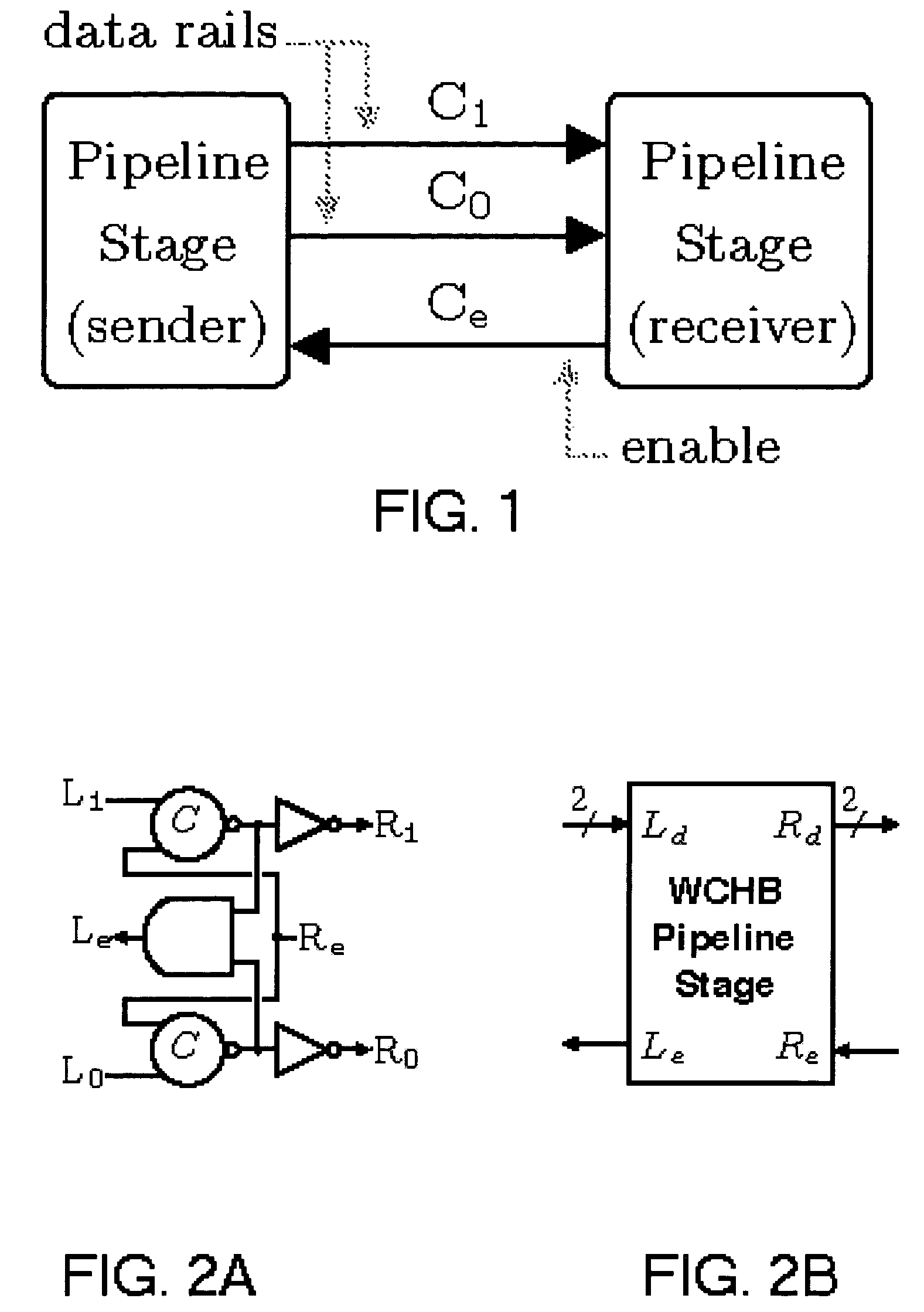
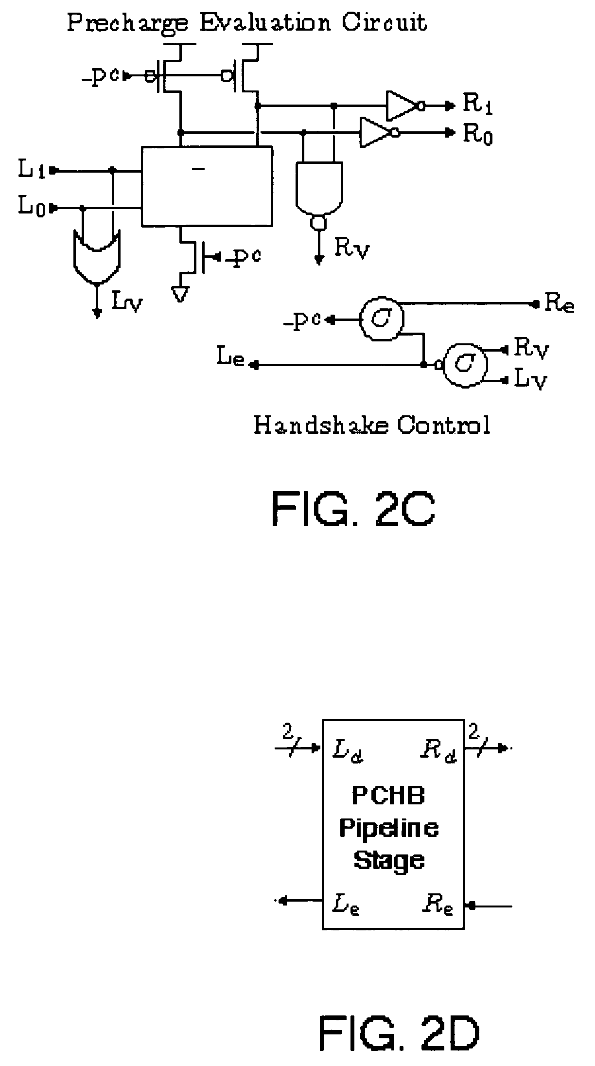
[0038]Before a discussion of the preferred embodiments of the present invention is presented, the basic asynchronous circuits that are employed as the building blocks in the preferred embossments will be discussed. The class of asynchronous circuits employed in the preferred embodiments is known as quasi-delay-insensitive (QDI). QDI circuits are designed to operate correctly under the assumption that gates and wires have arbitrary finite delay, except for a small number of special wires known as isochronic forks that can safely be ignored for the circuits in the preferred embodiments. Although transistors can be sized to adjust circuit delays, this only affects the performance of a circuit and not its correctness. The asynchronous systems that form the preferred embodiments can be viewed as a collection of concurrent hardware processes that communicate with each other through message-passing channels. The messages that are passed through the channels consist of atomic data items cal...


PUM


Abstract

High-performance, highly pipelined asynchronous FPGAs employ a very fine-grain pipelined logic block and routing interconnect architecture. These FPGAs, which do not use a clock to sequence computations, automatically “self-pipeline” their logic without the designer needing to be explicitly aware of all pipelining details. The FPGAs include arrays of logic blocks or cells that include function units, conditional units and other elements, each of which is constructed using basic asynchronous pipeline stages, such as a weak condition half buffer and a precharge half buffer.

Description

CROSS REFERENCE TO RELATED APPLICATIONS[0001]This application claims the benefit, under 35 U.S.C. 119(e), of U.S. Provisional Application No. 60 / 495,897, filed Aug. 19, 2003, which is hereby incorporated by reference in its entirety.GOVERNMENT SPONSORSHIP STATEMENT[0002]This invention arose out of research that was supported in part by the Multidisciplinary University Research Initiative (MURI) under the Office of Naval Research Contract N00014-00-1-0564, and in part by an NSF CAREER award under contract CCR 9984299. The US Government has certain rights in the invention.BACKGROUND OF THE INVENTION[0003]1. Field of the Invention[0004]The present invention relates in general to pipelined asynchronous logic circuits that can be employed to implement programmable logic circuits such as Field Programmable Gate Arrays (FPGAs) without the use of a global or system clock. Logic blocks formed from fine grain pipelined logic elements, each including only a small amount of logic, can be used t...

Claims


Application Information

Patent Timeline
Patent Type & Authority Patents(United States)
IPC IPC(8): H03K19/173H03K19/177
CPCH03K19/17736
Inventor TEIFEL, JOHN R.MANOHAR, RAJIT
Owner CORNELL RES FOUNDATION INC
Why Eureka
Try Eureka