Method for resonance identification in hard disk drives

a hard disk drive and resonance identification technology, applied in the field of resonance identification in hard disk drives, can solve the problem of time-consuming and laborious procedure of sweeping the excitation signal

Inactive Publication Date: 2007-01-02
SAMSUNG ELECTRONICS CO LTD
View PDF3 Cites 22 Cited by
  • Summary
  • Abstract
  • Description
  • Claims
  • Application Information

AI Technical Summary

Problems solved by technology

Sweeping the excitation signal can be a time consuming procedure.

Method used


Image

  • Method for resonance identification in hard disk drives
  • Method for resonance identification in hard disk drives
  • Method for resonance identification in hard disk drives

Examples


Embodiment Construction

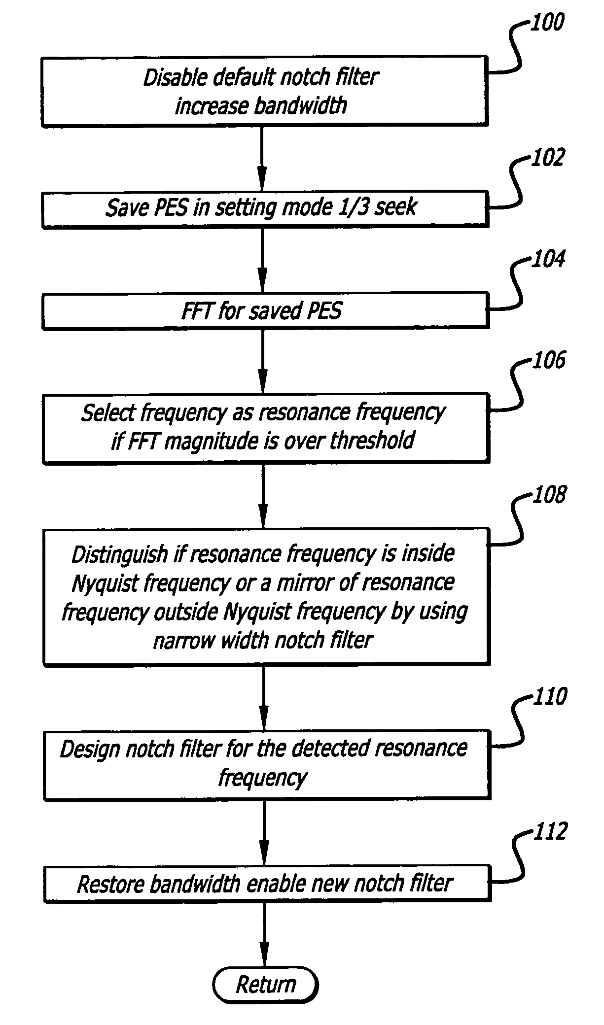
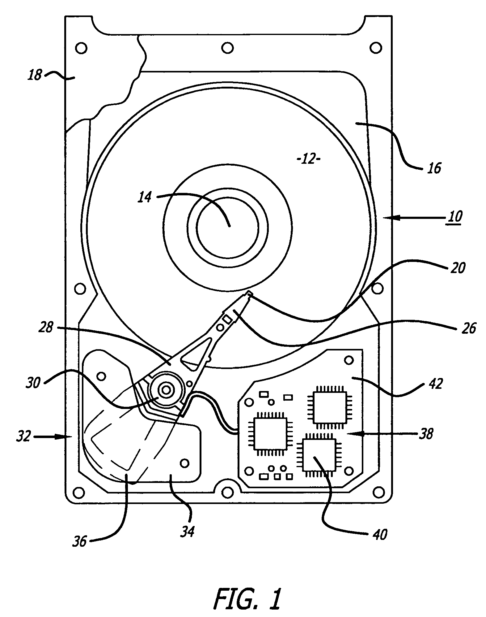
[0013]Disclosed is a hard disk drive that redefines a notch filter of the drive. The update process may include initially disabling all notch filters and inducing a seek operation of the disk drive heads. A position error signal is read during a settling time of the seek operation and processed to determine the frequency of the signal. The frequency is selected as a resonant frequency if the position error signal magnitude exceeds a threshold value. The notch filter is then redefined in accordance with the selected resonant frequency. The controller may also perform a routine to determine whether the resonant frequency is above or below a Nyquist frequency. Unlike prior art techniques, the method disclosed can obtain the resonant frequency without sweeping the excitation signal of the disk drive voice coil motor.

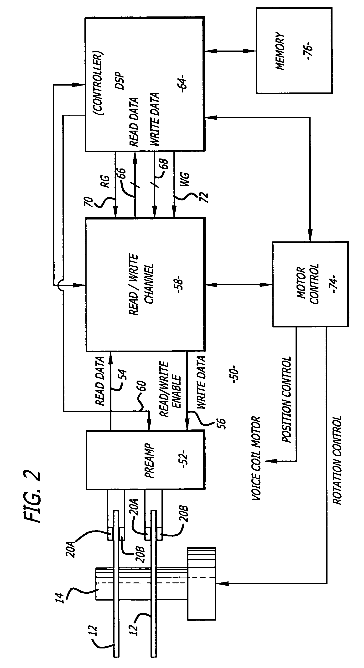
[0014]Referring to the drawings more particularly by reference numbers, FIG. 1 shows an embodiment of a hard disk drive 10 of the present invention. The disk drive 10 may in...


PUM

PropertyMeasurementUnit
resonant frequencyaaaaaaaaaa
Nyquist frequencyaaaaaaaaaa
frequencyaaaaaaaaaa

Abstract

A hard disk drive that redefines a notch filter of the drive. The update process may include initially disabling all notch filters and inducing a seek operation of the disk drive heads. A position error signal is read during a settling time of the seek operation and processed to determine the frequency of the signal. The frequency is selected as a resonant frequency if the error signal magnitude exceeds a threshold value. The notch filter is then redefined in accordance with the selected resonant frequency. The controller may also perform a routine to determine whether the resonant frequency is above or below a Nyquist frequency. Unlike prior art techniques, the method disclosed can obtain the resonant frequency without sweeping the excitation signal of the disk drive voice coil motor.

Description

BACKGROUND OF THE INVENTION[0001]1. Field of the Invention[0002]The present invention relates to a method for redefining a notch filter of a hard disk drive.[0003]2. Background Information[0004]Hard disk drives contain a plurality of magnetic heads that are coupled to rotating disks. The heads can magnetize and sense the magnetic fields of the disk to write and read data, respectively. The heads are coupled to an pivoting actuator arm that has a voice coil motor.[0005]Data is typically stored on tracks that extend radially across the disk surfaces. The voice coil motor can be energized to pivot the actuator arm and move the heads to different track locations. Each track is typically divided into a number of sectors. Each sector contains a number of servo bits that are read to produce a position error signal (PES). The PES is processed and used to center the heads on the tracks in accordance with a servo routine.[0006]Movement of the heads from track to track may induce a resonant mo...

Claims


Application Information

Patent Timeline
Patent Type & Authority Patents(United States)
IPC IPC(8): G11B5/596
CPCG11B5/5534
Inventor PARK, CHEOL HOONCHU, SANG HOONLEE, YONG GWON
Owner SAMSUNG ELECTRONICS CO LTD
Why Eureka
Try Eureka