Radiographic image processing method, radiographic image processing apparatus, radiographic image processing system, program, computer-readable storage medium, image diagnosis assisting method, and image diagnosis assisting system

a radiographic image processing and radiographic image technology, applied in the field of radiographic image processing apparatus, radiographic image processing system, image diagnosis assisting method, image diagnosis assisting system, can solve the problems of small amount of information available in cad, low reliability of detailed image information obtained in this fashion, and insufficient recognition of information useful for doctors

Active Publication Date: 2007-01-02
CANON KK
View PDF20 Cites 24 Cited by
  • Summary
  • Abstract
  • Description
  • Claims
  • Application Information

AI Technical Summary

Problems solved by technology

Conversely, it is probably thought that, in not a few cases, doctors cannot sufficiently recognize information useful for diagnosis that could be obtained from observing a moving-state image of the chest.
Further, because the moving-state image is generally radiographed with a small dose, reliability of detailed image information obtained in this fashion is relatively low.
Consequently, the amount of information available in CAD is small, which has been one factor causing a stagnation in detection accuracy of the CAD.

Method used


Image

  • Radiographic image processing method, radiographic image processing apparatus, radiographic image processing system, program, computer-readable storage medium, image diagnosis assisting method, and image diagnosis assisting system
  • Radiographic image processing method, radiographic image processing apparatus, radiographic image processing system, program, computer-readable storage medium, image diagnosis assisting method, and image diagnosis assisting system
  • Radiographic image processing method, radiographic image processing apparatus, radiographic image processing system, program, computer-readable storage medium, image diagnosis assisting method, and image diagnosis assisting system

Examples


first embodiment

(First Embodiment)

[0051]This first embodiment includes the operations of steps F1 to F5 shown in a flowchart of FIG. 4. The operations of the steps F1 to F5 are described below in the order named.

[0052]First, a description is made of the step F1 of “obtaining a moving state image and a still image of the chest”.

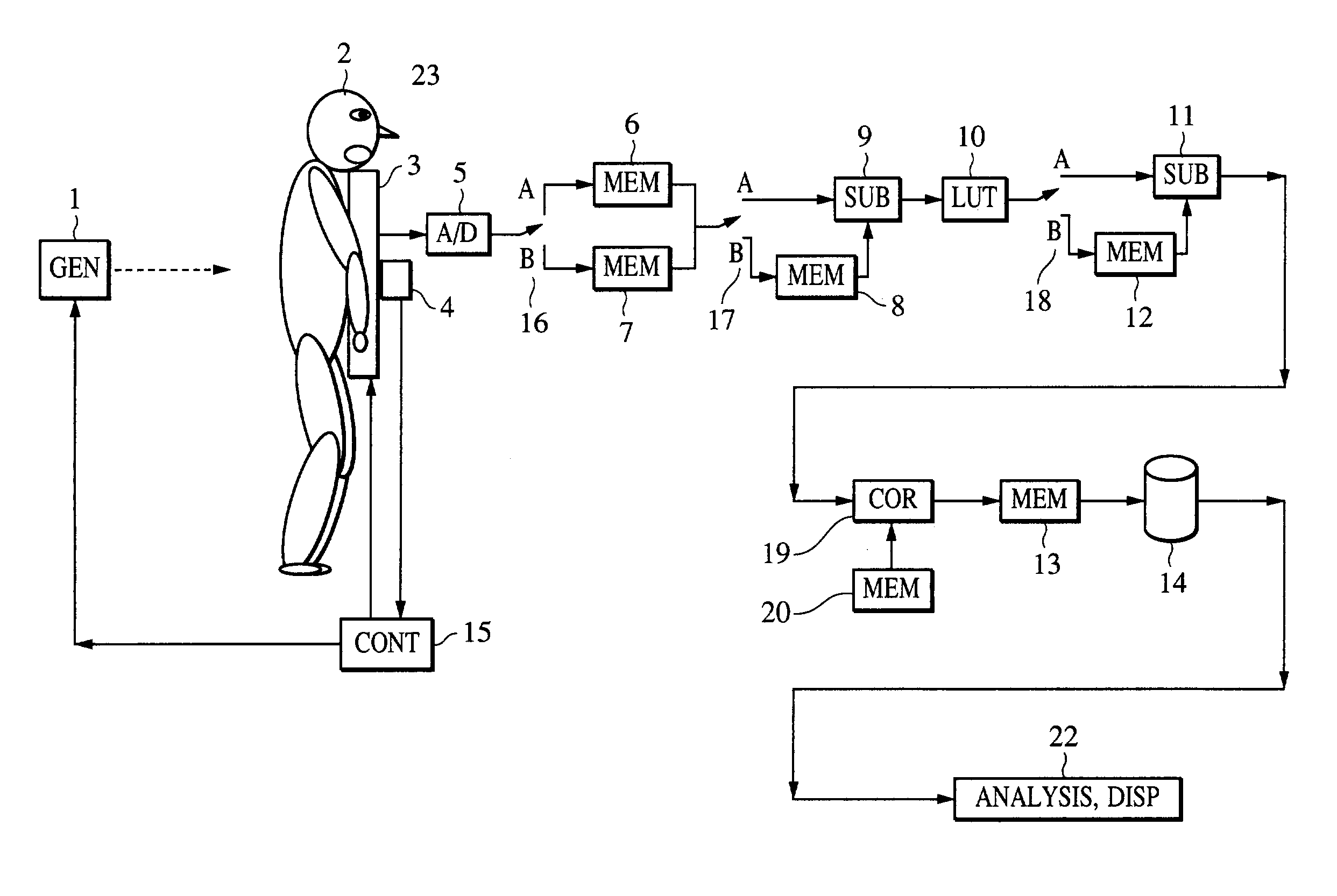
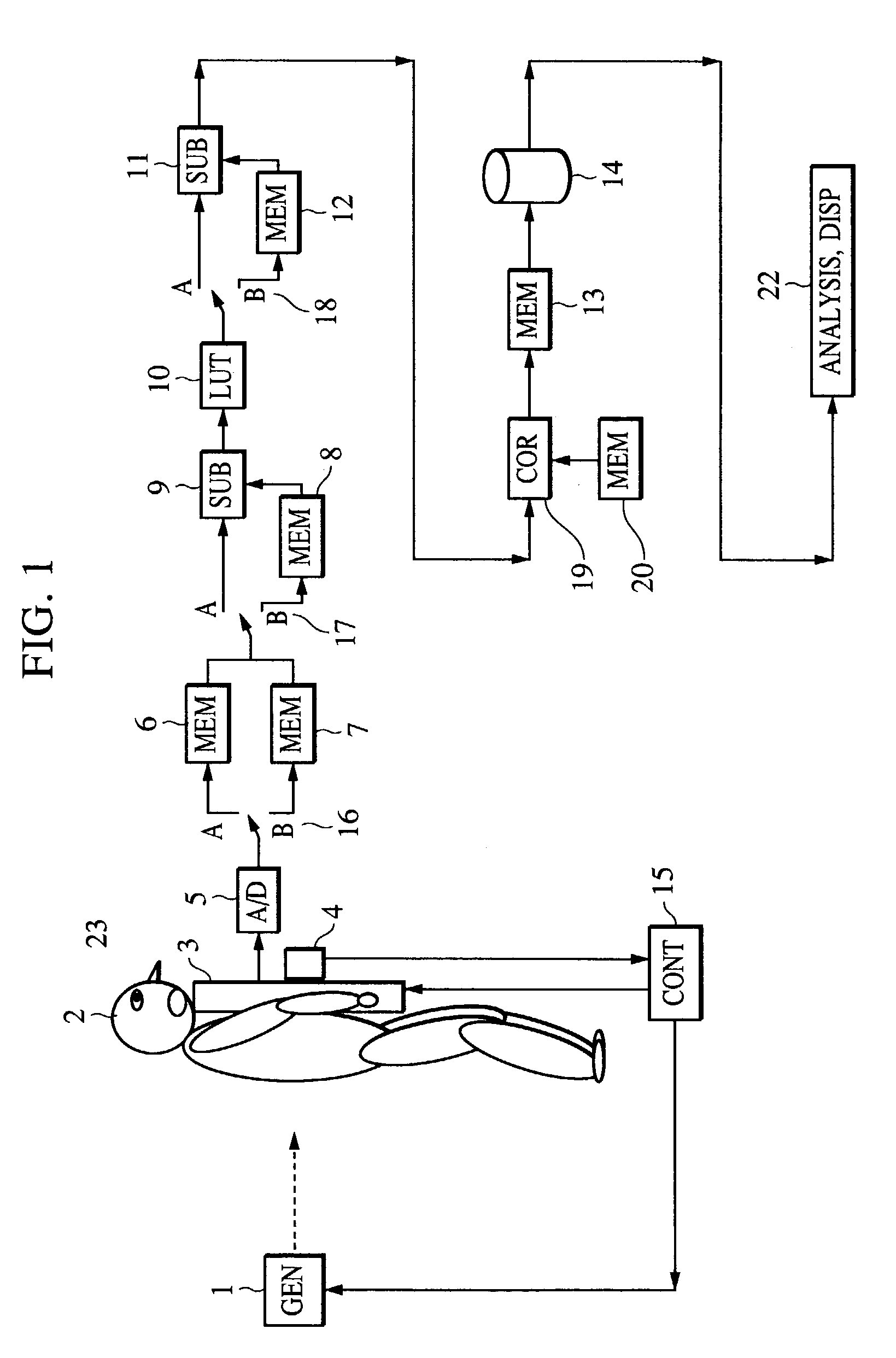
[0053]FIG. 1 is a block diagram schematically showing the first embodiment of the present invention. An X-ray generator (X-ray source) 1 radiates X-rays in the direction the dotted-line arrow as shown. In this case, for radiographing the chest of a human body (patient) 2, i.e., a subject (also sometimes preferred to as the “object”), the X-rays enter the human body from the back side, and a radiographic image of the chest is obtained. A flat panel detector 3 for imaging a distribution of the X-ray intensity includes a plurality of image receiving devices (referred to simply as “pixels”), which are arrayed on an image receiving surface in a matrix pattern and correspond to a p...

second embodiment

(Second Embodiment)

[0078]This second embodiment differs from the first embodiment in further comprising an image analysis (CAD, or Computer-Aided Diagnosis) step of detecting the disease-suspicious location by means of a computer.

[0079]FIG. 9 is a flowchart showing the processing executed in this second embodiment. A description of steps F1 to F4, which are the same as those in FIG. 4, is omitted here.

[0080]In step F6, the still image is analyzed to specify the disease-suspicious location (referred to also as the “region of interest”). Some examples of the image processing in this step are stated in detail in papers given below:[0081]Shigehiko Katsuragawa, et al., “Possibility of Computer-Aided Diagnosis for Interstitial Diseases”, Journal of Japan Radiological Society, 50: 753–766, 1990; and[0082]Yasuo Sasaki, et al., “Quantitative Evaluation of Pneumoconiosis Reference Radiographs with Texture Analysis”, Journal of Japan Radiological Society, 52: 1385–1393, 1992. The disclosures o...

third embodiment

(Third Embodiment)

[0085]FIG. 10 is a flowchart showing the processing executed in this third embodiment. A description of the steps F1 to F4, which are the same as those in FIG. 4, is omitted here. In next step F9, the moving-state image is analyzed. With the analysis of the moving-state image, the disease-suspicious (disease-candidate) location (referred to also as the “region of interest”) can be detected through computer-aided image analysis based on changes in motion vectors, in density at a particular part and in area size at each part.

[0086]In step F10, a moving mark is put on the moving-state image at the location detected in the step F9.

[0087]Then, in step F11, marking is made on the corresponding location (referred to also as the “region of interest”) in the still image. As a result, the diagnosis doctor is able to observe both the still image and the moving-state image and to make a diagnosis with high certainty while referring to the result of image analysis executed by t...


PUM


Abstract

This invention provides a radiographic image processing method of processing a group of radiographs including a moving-state radiographic image consisting of a plurality of radiographs representing a moving state of an object. The method includes specifying a region of interest for a plurality of radiographs included in the group of radiographs, and outputting diagnosis assisting information for assisting in diagnosis based on the group of radiographs, in accordance with the specified region of interest.

Description

BACKGROUND OF THE INVENTION[0001]1. Field of the Invention[0002]The present invention relates to a radiographic image processing method, a radiographic image processing apparatus, a radiographic image processing system, a program, a computer-readable storage medium, an image diagnosis assisting method, and an image diagnosis assisting system.[0003]2. Description of the Related Art[0004]Techniques for utilizing the ability of radiation such as X-rays to pass through many or most materials, and imaging a distribution of transmittance of the radiations have been the basis for development of a great deal of modern medical technology. Since the discovery of X-rays, a distribution of X-ray intensity has been imaged by a method of converting the distribution of X-ray intensity to visible light with a phosphor, forming a latent image on a silver-salt film with the visible light, and then developing the latent image. Recently, when obtaining an X-ray image in digital form, a method employing...

Claims


Application Information

Patent Timeline
Patent Type & Authority Patents(United States)
IPC IPC(8): G06K9/00A61B6/00A61B6/02G06T1/00G06T7/20G06T13/00G06T13/80
CPCA61B6/02A61B6/5217A61B6/469G16H50/30
Inventor INOUE, HITOSHI
Owner CANON KK
Why Eureka
Try Eureka