
Electronic instrument having first and second operation units

a technology of operation unit and display panel, which is applied in the field of electronic instruments, can solve the problems of difficult visual recognition of the operation status of the instrument itself, and achieve the effect of reducing the displacement from the instrument body and increasing the display area of the display panel

Inactive Publication Date: 2007-01-02
PIONEER CORP
View PDF7 Cites 13 Cited by
  • Summary
  • Abstract
  • Description
  • Claims
  • Application Information

AI Technical Summary

Benefits of technology

The invention is an electronic instrument that allows for easy visual recognition of its operation status. The instrument has a first and second operation unit that can be moved relative to the instrument body. The exposed planes of the first and second operation units are exposed when the instrument is in a certain position, allowing for the display panels to be increased in size. The first and second operation units can be individually moved to different positions, minimizing interference with other components of the instrument. The instrument also has a recording medium inserting slot that can be covered with the second operation unit, allowing for secure insertion of a recording medium. The second operation unit can be moved in a way that its exposed planes do not overlap, preventing interference with other components of the instrument. The first and second operation units can be detached from the instrument body, allowing for easier visual recognition of the information displayed on the display panels.

Problems solved by technology

In this way, the conventional electronic instrument 101 has a tendency of making the operation status of the instrument itself difficult to recognize visually.

Method used


Image

  • Electronic instrument having first and second operation units
  • Electronic instrument having first and second operation units
  • Electronic instrument having first and second operation units

Examples


Embodiment Construction

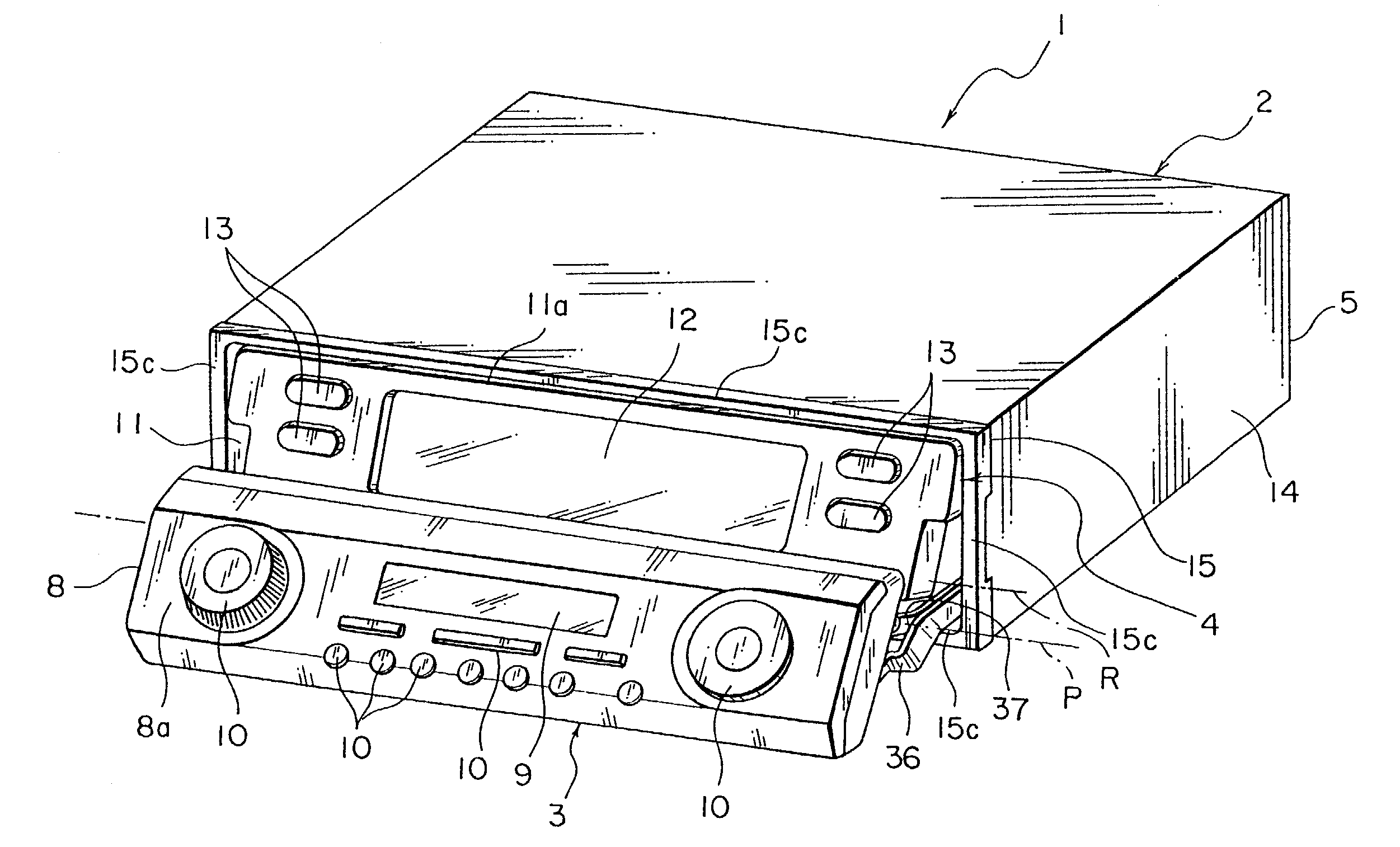
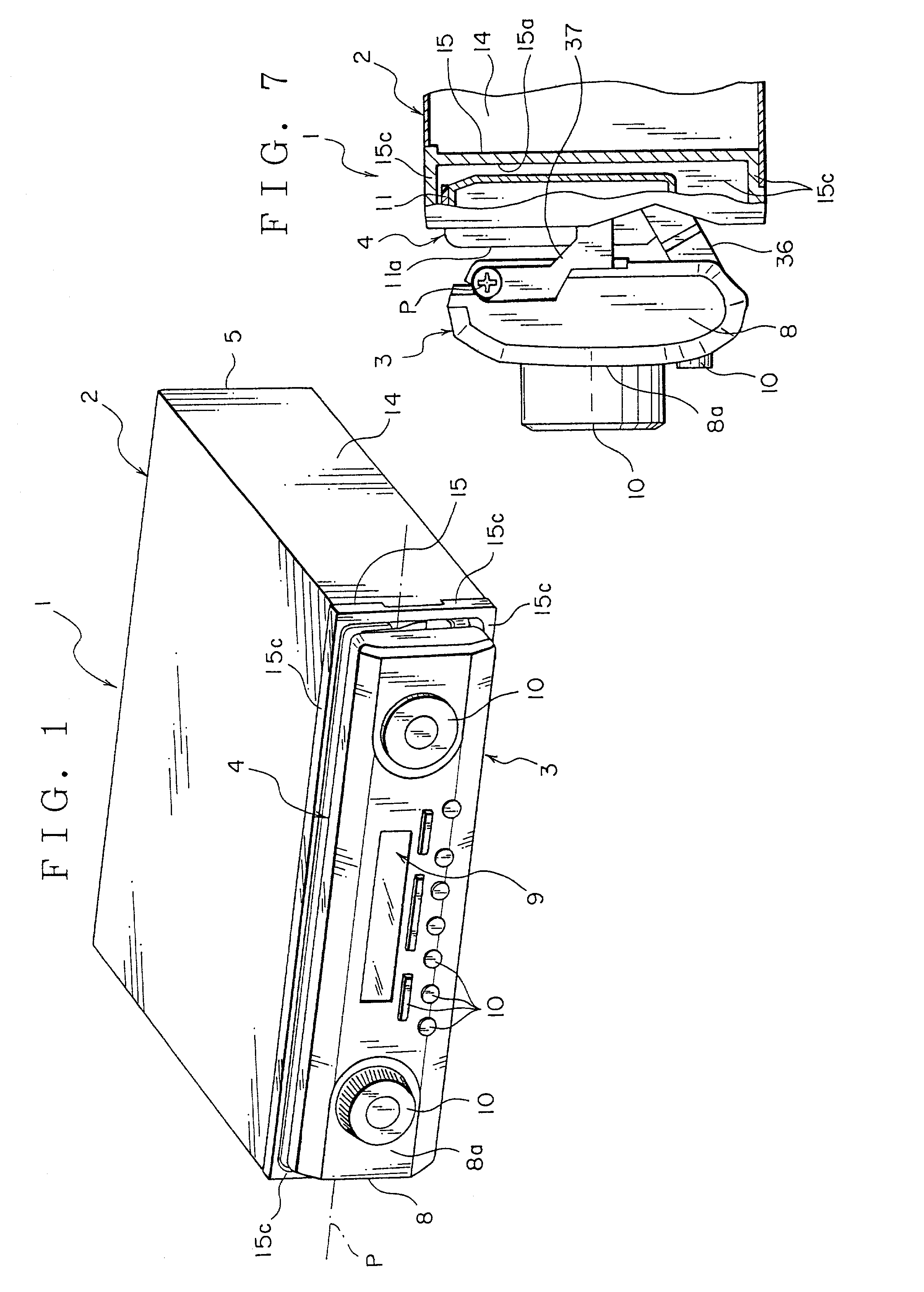
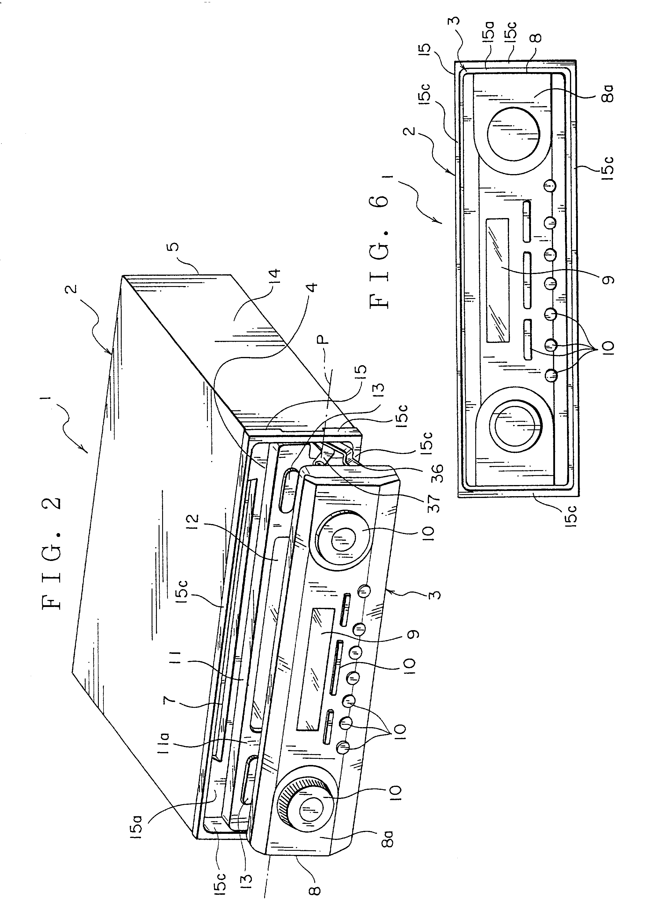
[0087]Referring to FIGS. 1 to 26, an explanation will be given of electronic instrument 1 according to a first embodiment of this invention.

[0088]The electronic instrument 1 is mounted on an instrument panel (“inpane”) of a vehicle which is a moving body. The electronic instrument includes various car audio devices such as a compact disk (hereinafter referred to as CD) player which incorporates a compact disk (CD) serving as a recording medium to play back the information recorded on the CD as sound and an AM / FM tuner which receives AM / FM broadcasting radio wave to produce the received information as sound.

[0089]As seen from FIGS. 1 to 3, the electronic instrument 1 includes an instrument body 2, a first operation unit 3 serving as a first driven unit, a second operation unit 4 serving as a second driven unit and a driving mechanism 6 (shown in FIGS. 4 and 5). The instrument body 2 includes a chassis 5 shaped like a flat box and an CD player, AM / FM tuner, etc. which are accommodated...


PUM

PropertyMeasurementUnit
widthaaaaaaaaaa
electricalaaaaaaaaaa
shapeaaaaaaaaaa

Abstract

An electronic instrument 1 includes an instrument body 2, a first operation unit 3, a second operation unit 4 and a drive mechanism. The first operation unit 3 and the second operation unit 4 are moved over a first position, a second position and a third position by the drive mechanism. At the first position, the first operation unit 3 covers the second operation unit 4. The first operation unit 3 and the second operation unit 4 move downward from the first position. At the third position, a recording medium insertion slot is exposed. The first operation unit 3 moves downward from the third position whereas the second operation unit 4 moves upward from the third position. At the second position, the exposed planes 8a and 11a are exposed. In the above configuration, there is provided an electronic instrument which can easily visually recognize the operating state of itself.

Description

BACKGROUND OF THE INVENTION[0001]1. Field of the Invention[0002]This invention relates to electronic instrument such as an audio device which mounted on e.g. a vehicle which is a moving body.[0003]2. Description of the Related Art[0004]Conventional electronic instrument includes various car audio devices such as a compact disk (hereinafter referred to as CD) player, a mini-disc (MD) player, an AM / FM tuner, etc. which are mounted on an instrument panel (hereinafter referred to as “inpane”) of a vehicle which is a moving body. The car audio device is an electronic instrument 101 (FIG. 34) which incorporates e.g. the CD player and the AM / FM tuner which are accommodated in a box.[0005]The electronic instrument 101 as illustrated in FIG. 34 includes an instrument body 102 attached to the inpane and an operation unit 103 which is movably attached to the instrument body 102. The instrument body 102 is formed in a box shape. The instrument body incorporates the AM / FM tuner and a player for ...

Claims


Application Information

Patent Timeline
Patent Type & Authority Patents(United States)
IPC IPC(8): G11B33/02H05K5/02G11B17/032
CPCG11B17/032G11B33/027
Inventor SASAKI, TAKAHIROSHIMIZU, AKIRAKASAHARA, NOBUMITSU
Owner PIONEER CORP
Learn More