Circular saw for facilitating straight cuts and/or cuts at a desired angle relative to a workpiece edge

a circular saw and workpiece edge technology, applied in the field of circular saws, can solve the problems of not being able to achieve straight cuts, and achieve the effect of minimizing wheel slippag

Inactive Publication Date: 2007-01-09
PETRENKO ALEX
View PDF29 Cites 26 Cited by
  • Summary
  • Abstract
  • Description
  • Claims
  • Application Information

AI Technical Summary

Benefits of technology

[0006]One set of features for facilitating straight line cuts includes the bottom plate comprising at least two sets of wheels connected to the bottom plate, each set of wheels comprising an axle having at least two wheels fixed to the axle in a configuration that prevents rotation of the wheels relative to the axle. The bottom plate has an opening aligned with each wheel to allow the wheel to protrude through the opening. Each wheel comprises a non-slip feature, such as plurality of protrusions capable of biting into the workpiece, for minimizing slippage of the wheel on the workpiece. The sets of wheels may have a lowered configuration relative to the bottom plate in which the wheels protrude through the openings past the bottom surface of the bottom plate a sufficient distance to contact the workpiece, and a raised configuration relative to the bottom plate in which the wheels do not protrude through the openings past the bottom surface of the bottom plate. A toggle mechanism may be provided for raising and lowering the wheels.

Problems solved by technology

Although miter saws are known for making angled cuts on short workpieces, such as 2×4s, they are not useful for angled cuts that must extend for a substantial distance, such as on a plywood sheet.
Often, however, the user may stray from that line, making a cut that is not as straight as may be desired.

Method used


Image

  • Circular saw for facilitating straight cuts and/or cuts at a desired angle relative to a workpiece edge
  • Circular saw for facilitating straight cuts and/or cuts at a desired angle relative to a workpiece edge
  • Circular saw for facilitating straight cuts and/or cuts at a desired angle relative to a workpiece edge

Examples


combined embodiment

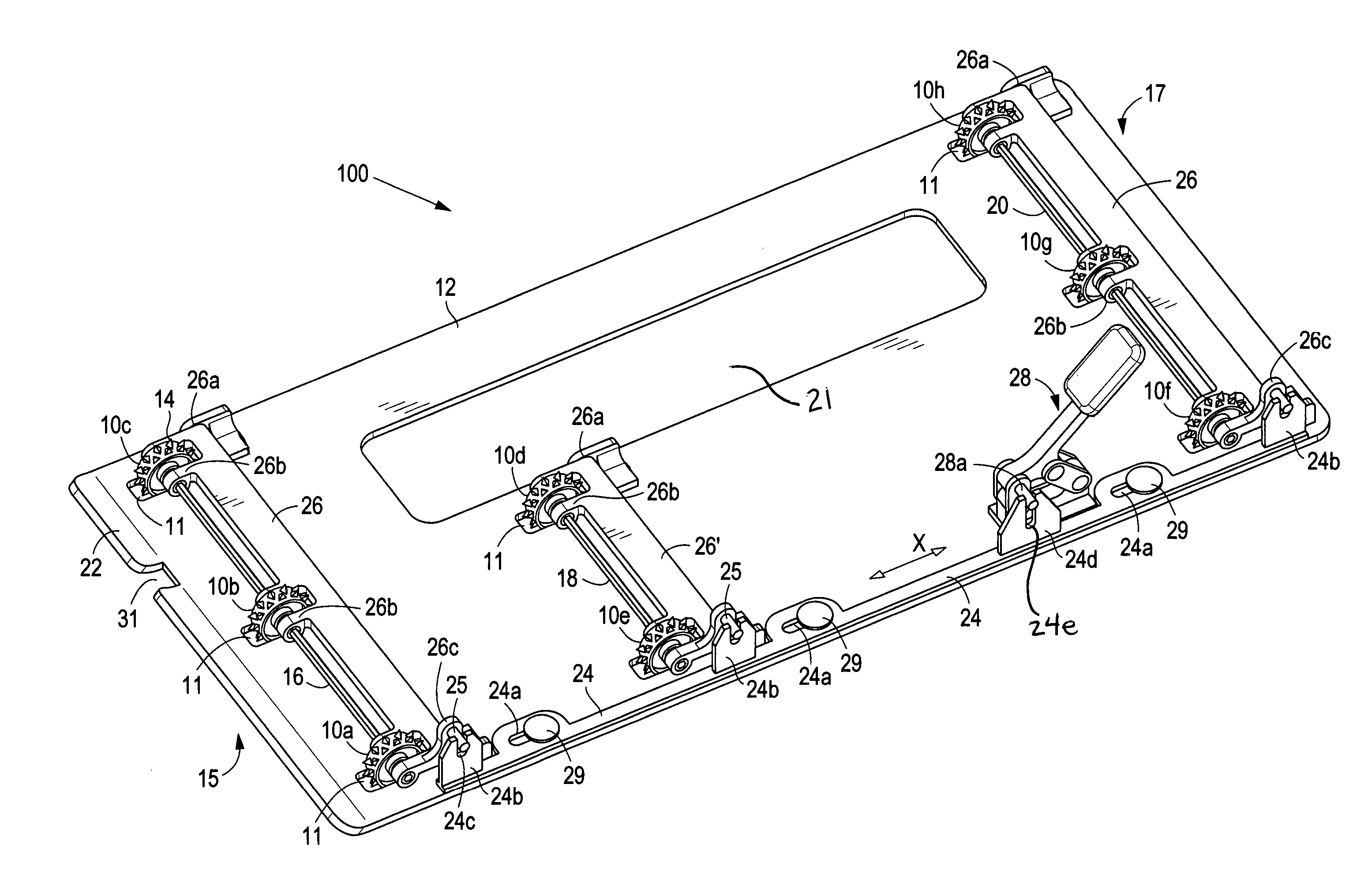
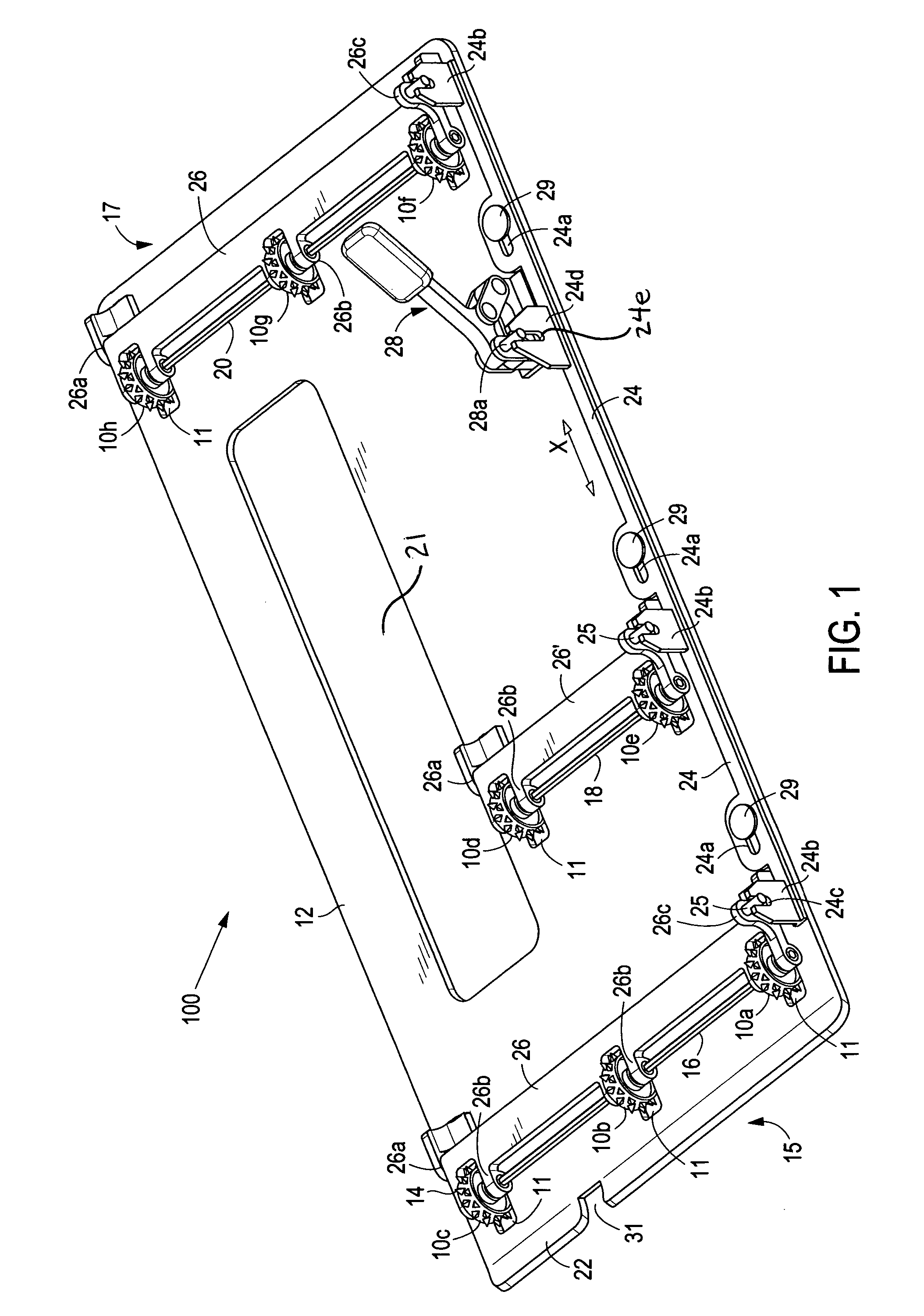
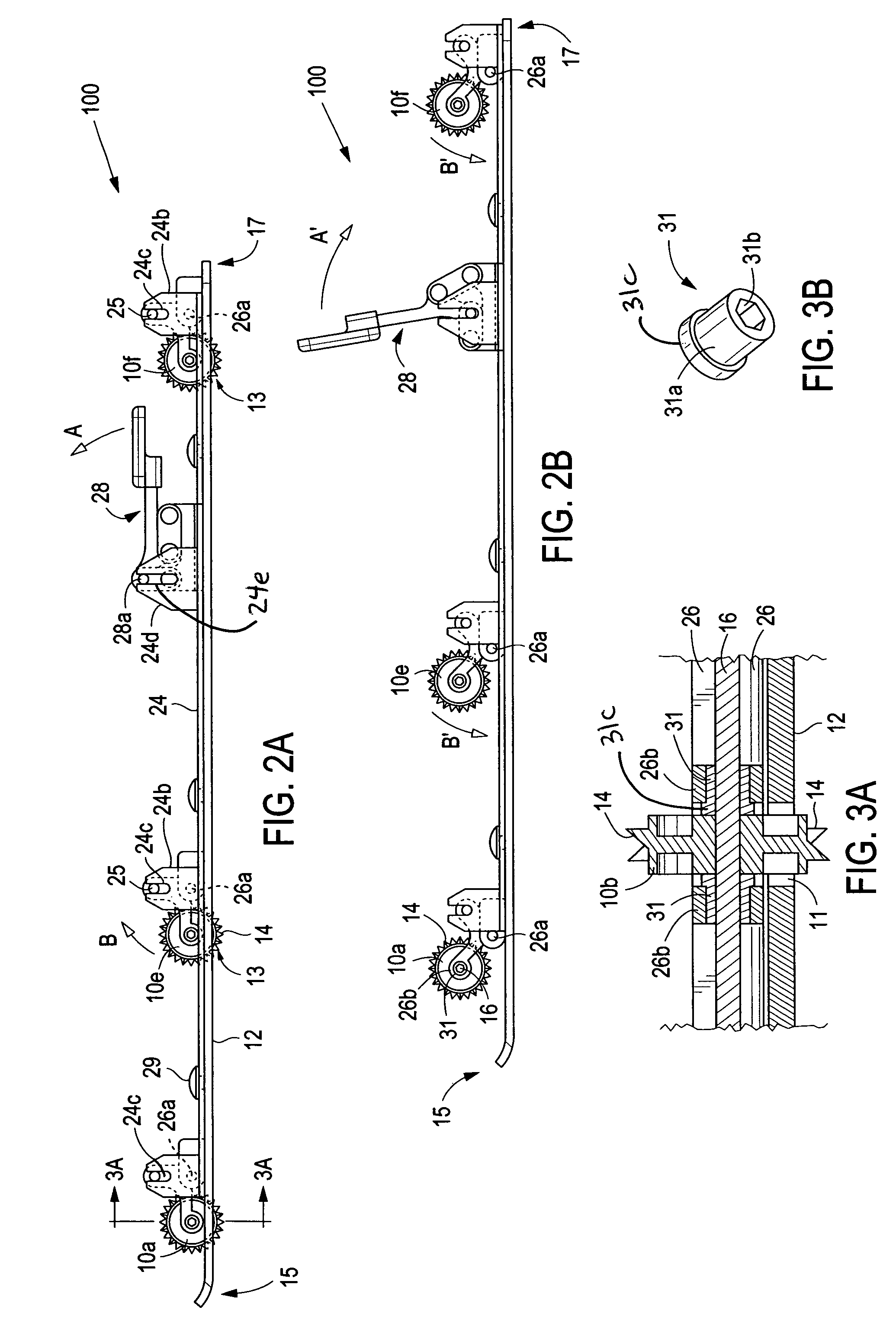
[0051]FIGS. 15–18 illustrate an embodiment that combines the features previously shown separately in FIGS. 1–3B and 12–14. Each of the identically numbered features shown in these figures is the same as and operates in the same manner as shown and described in the previous figures. To assure the spiked-wheel system and the guide system cooperate together, distance G2 that guide 42 protrudes above plate 12d must be less than the distance between (not shown) between plate 12d and the bottom of arms 26 to allow proper clearance for the slide to travel underneath the arms without hitting them. Similarly, the cam plate 144 should not be wider than the distance d between the adjacent wheels (10a and 10b, 10d and 10e, 10f and 10g) between which it travels. If guide 156 is wider than d, it should have a clearance G1 measured from the bottom surface of plate 12d that is greater than the distance G3 that spikes 14 extend below the bottom surface, so that the guide and the spikes do not interf...


PUM

PropertyMeasurementUnit
angleaaaaaaaaaa
angleaaaaaaaaaa
angleaaaaaaaaaa

Abstract

A power saw having one or more features for facilitating straight line and / or angled cuts, including (1) at least two sets of non-slip wheels connected to the bottom plate, each set of wheels comprising an axle having at least two wheels that are fixed to rotate at the same rate as the axle, (2) a transparent guide attached to and extending from the front of the bottom plate comprising a straight line marking aligned with the saw blade for alignment with a marking on the workpiece, and (3) a sliding guide adapted to travel within a slot in the bottom plate, the sliding guide adjustable to a desired angle relative to the saw blade and attached to a mechanism that provides resistance to rearward movement of the sliding guide and retracts the sliding guide back to a starting position after completion of a cut.

Description

CROSS-REFERENCE[0001]This invention claims priority of U.S. provisional patent application Ser. No. 60 / 538,572, filed Jan. 23, 2004, the contents of which are incorporated herein by reference.FIELD OF THE INVENTION[0002]This invention relates to saws, and more particularly for improvements to circular saws for facilitating straight cuts and / or cuts at a desired angle relative to an edge of the workpiece.BACKGROUND OF THE INVENTION[0003]Circular saws are well known in the art and are often used to cut a straight line over a substantial distance, for example on a sheet of plywood. Circular saws are also often needed to make cuts that are angled relative to the workpiece edge. Although miter saws are known for making angled cuts on short workpieces, such as 2×4s, they are not useful for angled cuts that must extend for a substantial distance, such as on a plywood sheet. In such circumstances, typically a line is drawn on the workpiece, such as with a ruler or chalk line, and the user f...

Claims


Application Information

Patent Timeline
Patent Type & Authority Patents(United States)
IPC IPC(8): B27B9/04B23D47/02B27B9/00
CPCB27B9/00B23D47/02
Inventor PETRENKO, ALEX
Owner PETRENKO ALEX
Why Eureka
Try Eureka