Seal arrangement

a seal arrangement and sealing technology, applied in the direction of liquid fuel engines, machines/engines, mechanical equipment, etc., can solve the problems of brush seals, leaf seal elements are still liable to suffer from so-called “blow-down” behaviour, bristles tend to wear rapidly, etc., to limit the lateral movement of the seal arrangemen

Inactive Publication Date: 2007-01-09
ROLLS ROYCE PLC
View PDF5 Cites 25 Cited by
  • Summary
  • Abstract
  • Description
  • Claims
  • Application Information

AI Technical Summary

Benefits of technology

[0010]Typically, recess portions in adjacent juxtaposed leaf seal elements coincide in order to define the passage therebetween. Furthermore, advantageously, recess portions in adjacent juxtaposed leaf seal elements are reciprocally shaped. Alternatively, recess portions in adjacent leaf seal elements are differentially shaped for element flexibility and performance.
[0014]Possibly, the present seal arrangement is mounted within a carriage whereby that carriage can be secured in a float chamber whereby radial displacement of the seal arrangement is resisted by a bias resistance created by an air flow presented to the float chamber. Possibly, the float chamber incorporates a retainer in order to limit lateral movement of the seal arrangement. Normally, this retainer will be secured at the back of the float chamber.

Problems solved by technology

Such brush seals have two distinct disadvantages when presented with high differential pressures.
Firstly, the bristles tend to wear rapidly and secondly, the bristles can be forced into a “locked” configuration where the bristles cannot move to accommodate excursions in the components to be sealed.
Unfortunately, such leaf seal elements are still liable to suffer from so-called “blow-down” behaviour if the pressure distribution above and below each leaf seal element is not balanced.
In such circumstances, leaf seal elements continue to suffer from premature wear unless a balancing upward force is provided in the form of an air film between the leaf seal element tip edge and the opposed component surface e.g. rotating surface.
Unfortunately, provision of either spacers between adjacent leaf seal elements or tapering of such leaf seal elements renders manufacture of a seal arrangement incorporating leaf seal elements difficult and the eventual seal arrangement is relatively inefficient and leaky in terms of seal effectiveness.

Method used


Image

  • Seal arrangement
  • Seal arrangement
  • Seal arrangement

Examples


Embodiment Construction

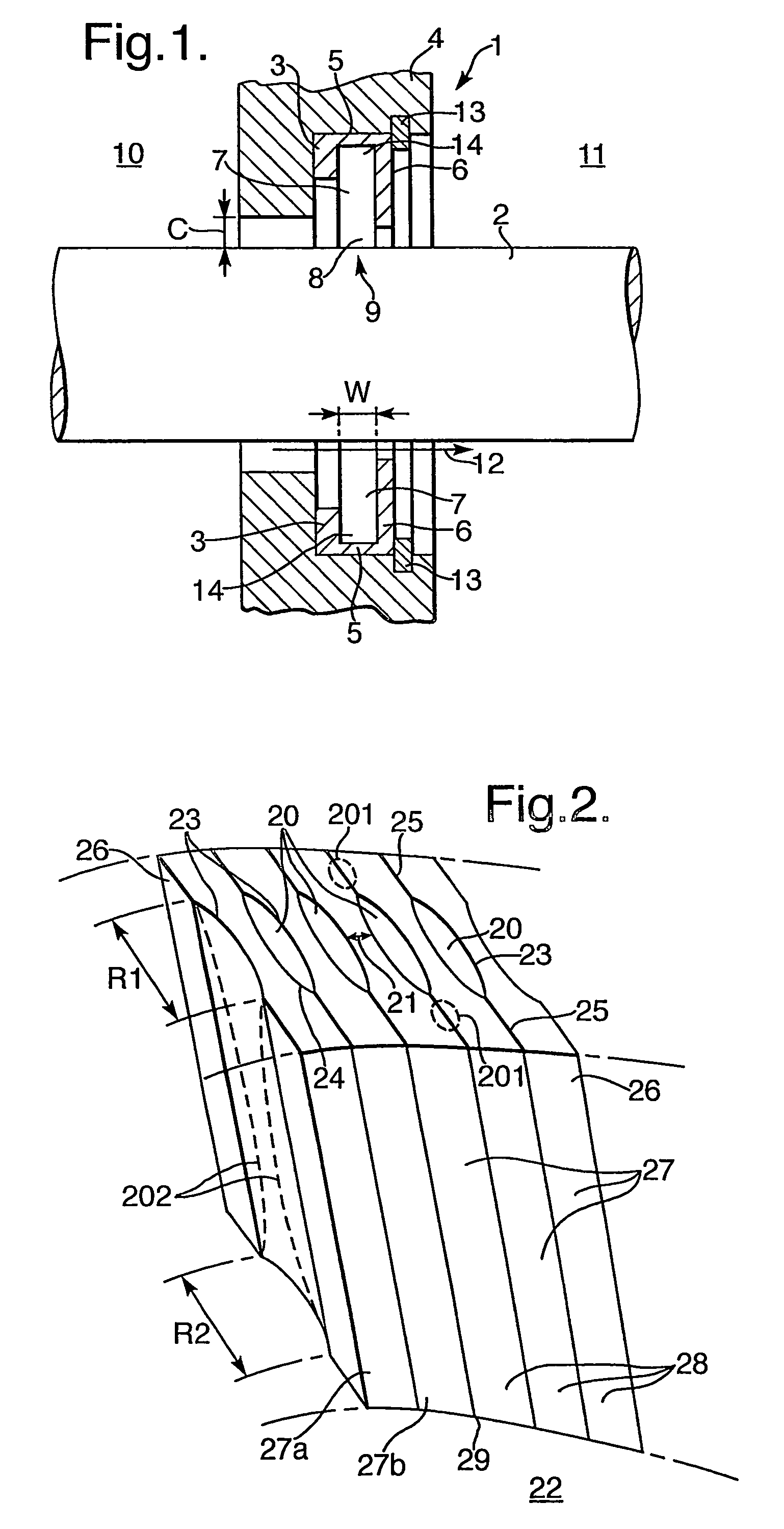
[0026]FIG. 1 is a schematic cross-section of a seal assembly 1 in accordance with the present invention arranged to provide a seal around a shaft 2. The seal assembly 1 incorporates a seal arrangement 3 secured within a housing 4. The seal arrangement 3 comprises a mounting 5 incorporating a back plate 6 within which a number of seal elements 7 are secured such that tip edges 8 of those elements 7 engage a surface 9 of the shaft component 2 in order to create the desired seal. Generally, the housing 4 will be part of a wall between respective chambers 10, 11. Furthermore, these chambers 10, 11 will be at differential pressures. Thus, the chamber 10 will be at a high pressure and the chamber 11 at a lower pressure such that the seal arrangement 3 and in particular the seal created by engagement between the tip edges 8 and the surface 9 retains that pressure differential. In such circumstances, there is a sealing direction 12 which illustrates lateral pressure on the element 7. In suc...


PUM


Abstract

A seal arrangement (73) is provided in which seal elements (77) incorporate passages (90) allowing an air flow to be presented to tip edges (78) of the seal elements, in order to create air suspension and diminish excessive wear. These passages (90) are created by recesses in the respective adjacent juxtaposed seal elements (77). In a seal assembly (71) a seal arrangement (73) is secured within a float chamber (70) whereby radial movement is allowed to accommodate for movements in the shaft (72). The radial movement is resisted by a bias created by air flow (86) into the float chamber (70). The air flow (86) may also be presented through the passages (90) in order to create the desired air suspension of the seal elements (77).

Description

[0001]This is a Continuation International Appln. No. PCT / GB2004 / 001115 filed Mar. 16, 2004 designated the U.S.FIELD OF THE INVENTION[0002]The present invention relates to seal arrangements and more particularly to a seal arrangement formed from a number of leaf seal elements.BACKGROUND OF THE INVENTION[0003]Traditionally, brush seals have been provided in order to present a seal between two components. The brush seals essentially comprise bristles which extend from one component to another. Tip portions of each bristle contacting the other component in order to provide a seal. Such brush seals have two distinct disadvantages when presented with high differential pressures. Firstly, the bristles tend to wear rapidly and secondly, the bristles can be forced into a “locked” configuration where the bristles cannot move to accommodate excursions in the components to be sealed.[0004]More recently the seal arrangements have been specified which relieve some of the disadvantages of brush s...

Claims


Application Information

Patent Timeline
Patent Type & Authority Patents(United States)
IPC IPC(8): F16J15/48F16J15/44
CPCF16J15/442F16J15/3292
Inventor NICHOLSON, RICHARDFORFAR, JAMES E.
Owner ROLLS ROYCE PLC
Why Eureka
Try Eureka