
Crimpable wire connector assembly

a technology of connectors and wires, applied in the direction of one-pole connections, coupling device connections, coupling device details, etc., can solve the problems of different kinds of stranded wires, difficult to ensure a positive connection by using threaded connecters alone, etc., to achieve fast, reliable and efficient

Inactive Publication Date: 2007-01-09
PPC BROADBAND INC
View PDF14 Cites 32 Cited by
  • Summary
  • Abstract
  • Description
  • Claims
  • Application Information

AI Technical Summary

Benefits of technology

The present invention provides a novel and improved stranded wire connecter assembly that can be used for interchangeable connection of different gauge wires to a post or terminal in a fast and reliable manner. The assembly is conformable for use as an end connecter for connection to the posts or terminals of electrical components, and wall outlets either as an end connecter or splice connection in an efficient and reliable manner. The assembly ensures a positive connection with maximum pull-out strength between the wire and the connector body, and each connector body is distinctly coded to indicate its intended use. The assembly also includes an adapter for crimping different sized wires into a connecter body, and a plurality of adapters for different gauge wires. The connecter bodies are conformable for use in splice connection assemblies and can be mounted in a wall plate or an electrical outlet.

Problems solved by technology

Stranded wires present a different kind of problem than conductor pins in terms of assuring a positive connection with maximum pull-out strength.
Also, the stranded wire is made up of different gauges or diameters depending on the desired signal strength thereby making it difficult to assure a positive connection by the utilization of threaded connecters alone.

Method used


Image

  • Crimpable wire connector assembly
  • Crimpable wire connector assembly
  • Crimpable wire connector assembly

Examples


Embodiment Construction

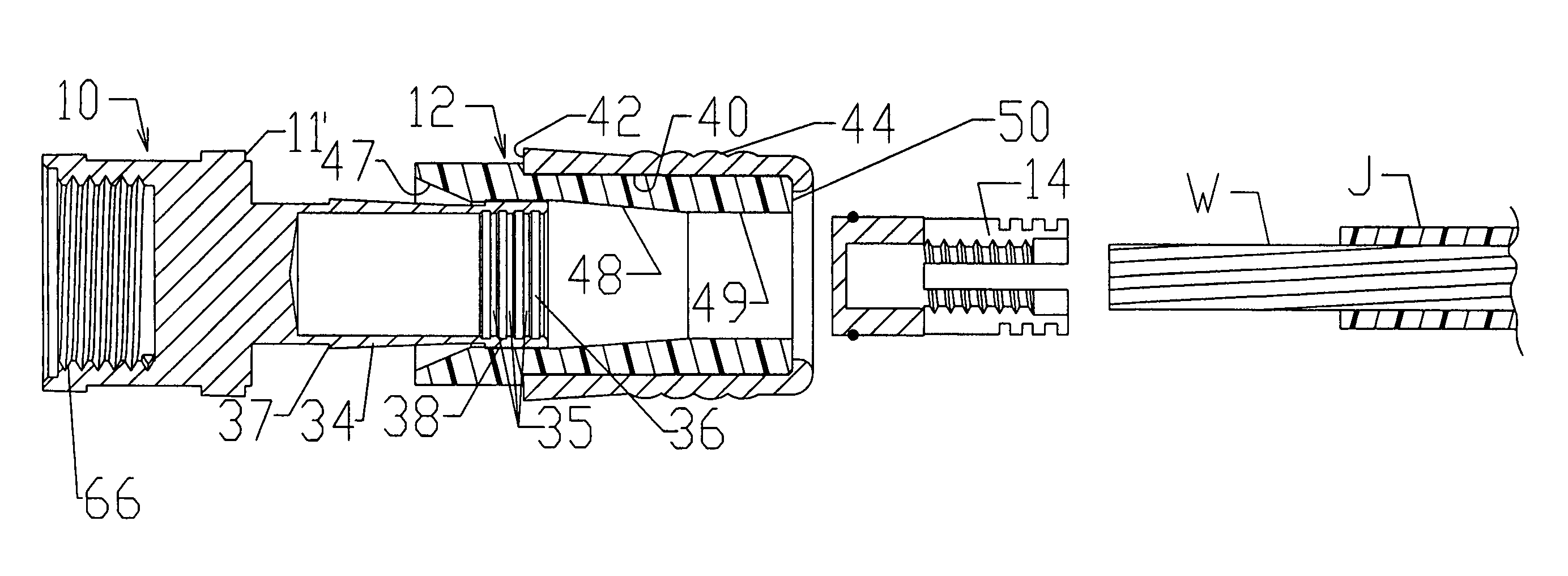
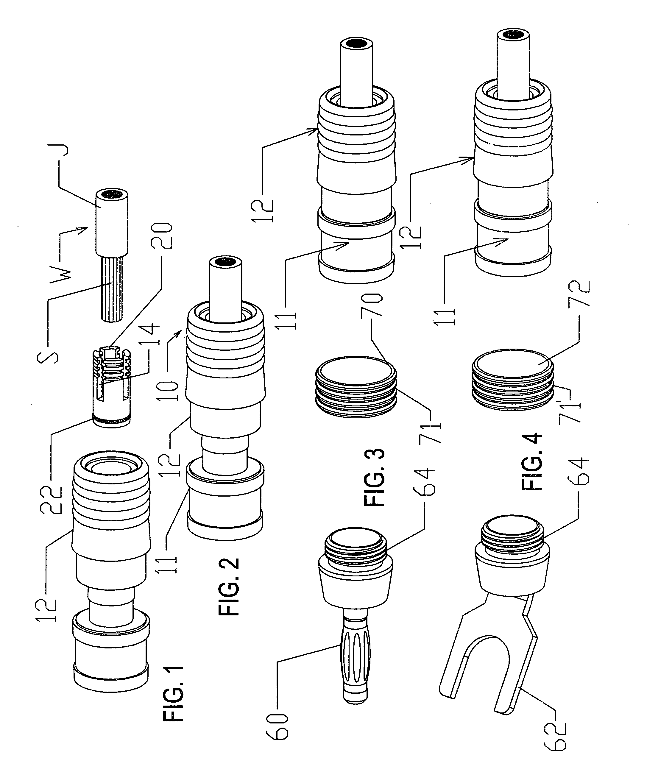
[0026]Referring in more detail to the drawings, FIGS. 1 and 2 illustrate a preferred form of wire connecter assembly 10 which is comprised of a generally cylindrical connecter body 11, a crimping member 12, an adapter sleeve 14 and a stranded wire W of standard construction. For example, the wire W is typically made up of an outer jacket J in surrounding relation to multiple strands S of wire which are bundled into a generally spiral configuration. As such, the wire-type connecter is the wire of choice for home entertainment systems and, for example, extends between and electrically connects the speaker terminals and tuner or amplifier terminals.

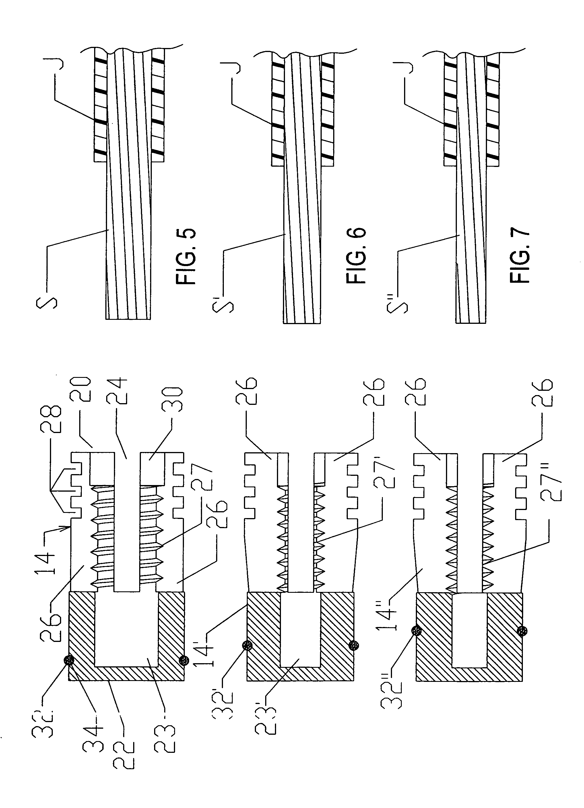
[0027]In order to securely attach the wire W to a terminal, the adapter sleeve 14 is made up of a generally cylindrical sleeve or tube which is open at one end 20 and closed at the opposite end 22. The adapter sleeve 14 is elongated and, as best seen from the detail views of FIGS. 5, 6 and 7, a plurality of circumferentially spaced longitudi...


PUM


Abstract

A crimpable universal wire connecter assembly is conformable for use in connecting electrical wires to a post or terminal of an electrical component or for splicing together to other connecter bodies and includes an adapter which is dimensioned to facilitate connection of different gauge wires into one size of connecter body.

Description

CROSS-REFERENCE TO RELATED APPLICATIONS[0001]This application is a continuation-in-part of patent application Ser. No. 10 / 654,808, filed 3 Sep., 2003 for ADAPTER FOR MINI-COAXIAL CABLE by Randall A. Holliday, now U.S. Pat. No. 6,935,892, issued 31 Aug., 2006, and incorporated by reference herein; a continuation-in-part of patent application Ser. No. 10 / 885,246, filed 6 Jul., 2004 for COAXIAL CABLE SPLICE CONNECTER ASSEMBLIES by Randall A. Holliday, now U.S. Pat. No. 7,059,900, issued 13 Jun., 2006, and incorporated by reference herein; and a continuation-in-part of patent application Ser. No. 10 / 752,287, filed 6 Jan. 2004 for CABLE CONNECTER HAVING INTERCHANGEABLE COLOR BANDS by Randall A. Holliday, now U.S. Pat. No. 7,044,771, issued 16 May, 2006, and incorporated by reference herein.BACKGROUND AND FIELD OF INVENTION[0002]This invention relates to wire connecters and more particularly relates to a novel and improved wire connecter assembly for interconnecting stranded wires to elec...

Claims


Application Information

Patent Timeline
Patent Type & Authority Patents(United States)
IPC IPC(8): H01R9/05H01R13/646
CPCH01R4/5025H01R2103/00H01R2101/00H01R24/542
Inventor HOLLIDAY, RANDALL A.
Owner PPC BROADBAND INC
Learn More