Sample holder for a charged particle microscope

a particle microscope and sample holder technology, applied in the direction of basic electric elements, electric discharge tubes, electrical apparatus, etc., can solve the problems of affecting the quality of sample holder, and requiring a lot of expertise and time, so as to achieve quick and reliable results, easy to use, and low cost

Active Publication Date: 2022-02-15
FEI CO
View PDF9 Cites 2 Cited by
  • Summary
  • Abstract
  • Description
  • Claims
  • Application Information

AI Technical Summary

Benefits of technology

[0011]The movable clamping member that is connected to said holder body allows for improved attachment of the sample carrier with said sample to said sample holder. Attachment can occur in a fast and reliable manner by moving the clamping member to the open position, placing the sample carrier in the recess, and simply moving the clamping member to the closed position again. As the clamping member is connected to the holder body, moving the clamping member between the open position and the closed position is relatively easy, and the movement of the clamping member provides a reliable way of securing the sample carrier in the sample holder. With this, a reliable, secure and fast way of mounting the sample carrier in the sample holder is obtained, with which the object as defined herein is achieved.
[0022]In an embodiment, the charged particle microscope comprises an actuator member for actuating said clamping member. In particular, said actuator member is arranged for pushing said clamping member towards the open position. In an embodiment, the clamping member is arranged to be urged towards the closed position. This way, the actuator member may be used to push the clamping member towards the open position, and moving the actuator member away from the clamping member ensures that the clamping member is moved to the closed position. This allows for easy and reliable positioning of the sample carrier in the sample holder.

Problems solved by technology

Fixing the very fragile grid, which is only about ten micrometers thick, to the TEM rod is a relatively risky and complex process.
Placing the circular ring requires a lot of expertise and takes time.
In this process, the sample is always subjected to the danger of being damaged.

Method used


Image

  • Sample holder for a charged particle microscope
  • Sample holder for a charged particle microscope
  • Sample holder for a charged particle microscope

Examples


Embodiment Construction

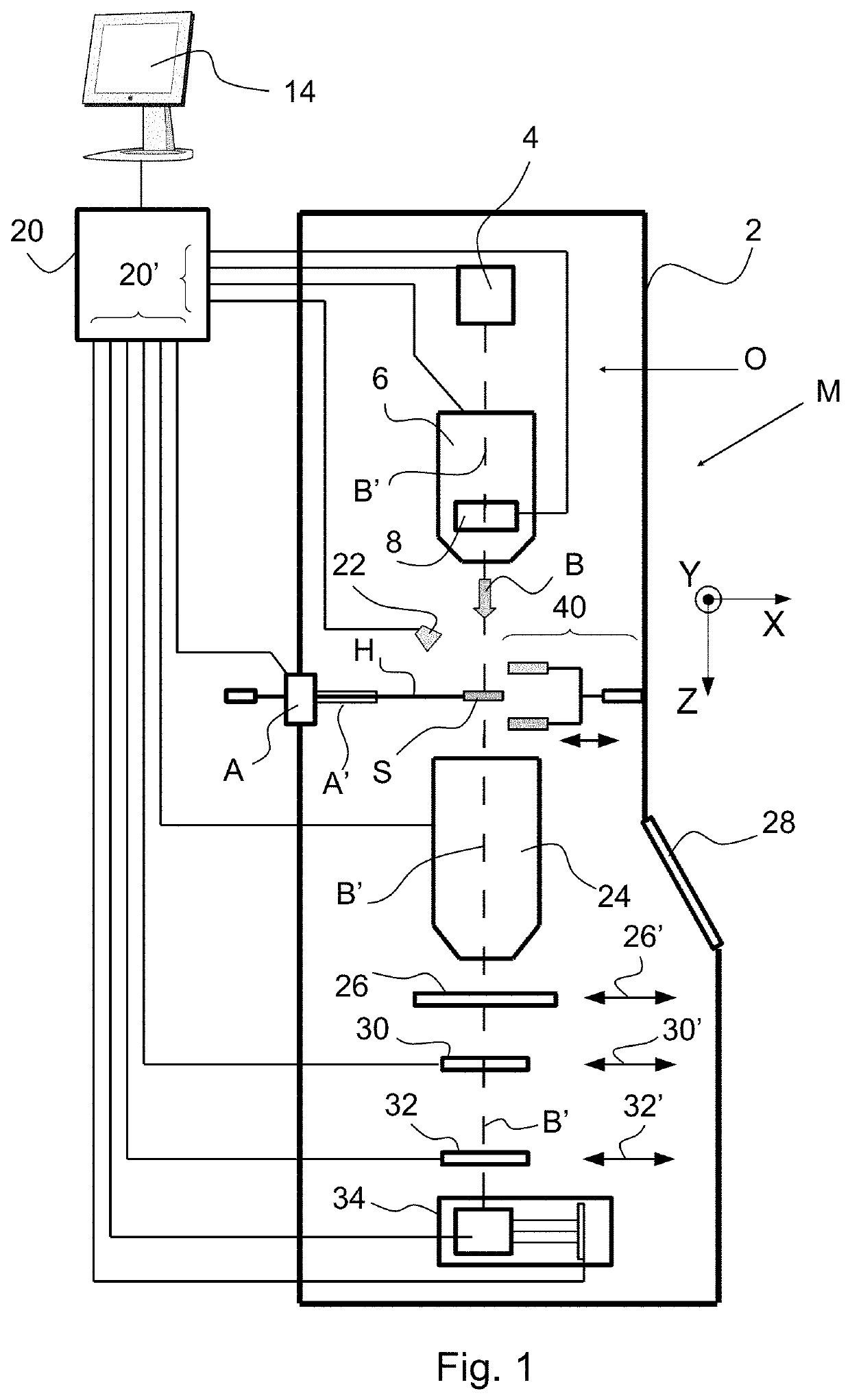
[0034]FIG. 1 (not to scale) is a highly schematic depiction of an embodiment of a charged-particle microscope M in which the sample holder as disclosed herein can be used. More specifically, FIG. 1 shows an embodiment of a transmission-type microscope M, which, in this case, is a TEM / STEM (though, in the context of the current invention, it could just as validly be a SEM, or an ion-based microscope, for example). In FIG. 1, within a vacuum enclosure 2, an electron source 4 produces a beam B of electrons that propagates along an electron-optical axis B′ and traverses an electron-optical illuminator 6, serving to direct / focus the electrons onto a chosen part of a sample S (which may, for example, be (locally) thinned / planarized). Also depicted is a deflector 8, which (inter alia) can be used to effect scanning motion of the beam B.

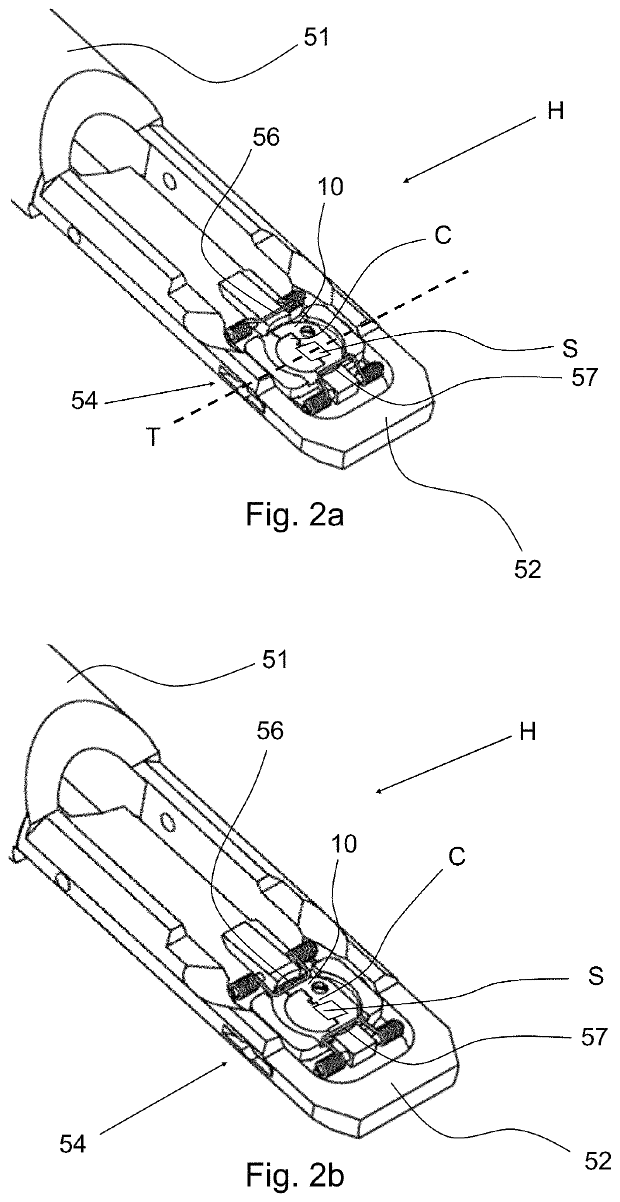
[0035]The sample S is held on a sample carrier C (not shown) that is mounted to sample holder H, and this sample holder H can be positioned in multiple degr...


PUM


Abstract

The disclosure relates to a sample holder for a charged particle microscope, comprising a holder body with a recess for releasably receiving a sample carrier with a sample therein; and at least one fixing element that is connectable to said holder body for fixing said sample carrier in said recess of said holder body. As described herein, said fixing element comprises a clamping member that is movably connected to said holder body, wherein said clamping member is movable between a closed and an open position, wherein in the open position said sample carrier can be placed in said recess, and wherein in said closed position said sample carrier can be locked in said recess. With this, a more reliable mounting of a sample carrier onto the sample holder can be established.

Description

BACKGROUND OF THE INVENTION[0001]In a transmission electron microscope (TEM), a parallel, high-energy beam of electrons with an energy of, for example, 300 keV is shot at the sample. As a result of interaction between the electrons and the sample, electrons in the beam will, for example, be deflected, loose energy or be absorbed, which can yield information about the sample. By arranging the electron beam to impinge in the correct manner upon, for example, a fluorescent screen and / or a CCD camera, the information can be rendered visible.[0002]The sample can also be irradiated by a focused beam, which beam is moved across the sample. In this mode of operation of a TEM, the so-called Scanning Transmission Electron Microscopy mode (STEM mode), position-dependent information in the form of secondary particles, such as secondary electrons and X-rays, is produced.[0003]TEM samples need to be very thin, for example less than 100 nm, preferably less than 50 nm. Presently, sample thicknesses...

Claims


Application Information

Patent Timeline
Patent Type & Authority Patents(United States)
IPC IPC(8): H01J37/20H01J37/26
CPCH01J37/20H01J37/261H01J37/26H01J2237/20H01J2237/2007
Inventor VAN DEN BOOGAARD, MATHIJS PETRUS WILHELMUSLAGRANGE, MARTIJNRODRIGUEZ, NESTOR HERNANDEZ
Owner FEI CO
Why Eureka
Try Eureka