Electrical fitting for snap in connection of cables

a technology of electrical fittings and cables, applied in the direction of insulated conductors, cable connections, coupling devices, etc., can solve problems such as obstruction of cables, and achieve the effect of reducing the diameter of the leading opening

Active Publication Date: 2007-01-09
ARLINGTON INDS
View PDF9 Cites 35 Cited by
  • Summary
  • Abstract
  • Description
  • Claims
  • Application Information

AI Technical Summary

Problems solved by technology

Prior art fittings utilizing frustoconical snap rings greatly reduce the diameter of the leading opening thereby causing an obstruction to any cables being inserted therein as a result of the necked down shoulder and the small leading opening.

Method used


Image

  • Electrical fitting for snap in connection of cables
  • Electrical fitting for snap in connection of cables
  • Electrical fitting for snap in connection of cables

Examples


Embodiment Construction

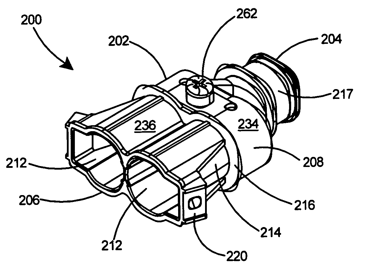
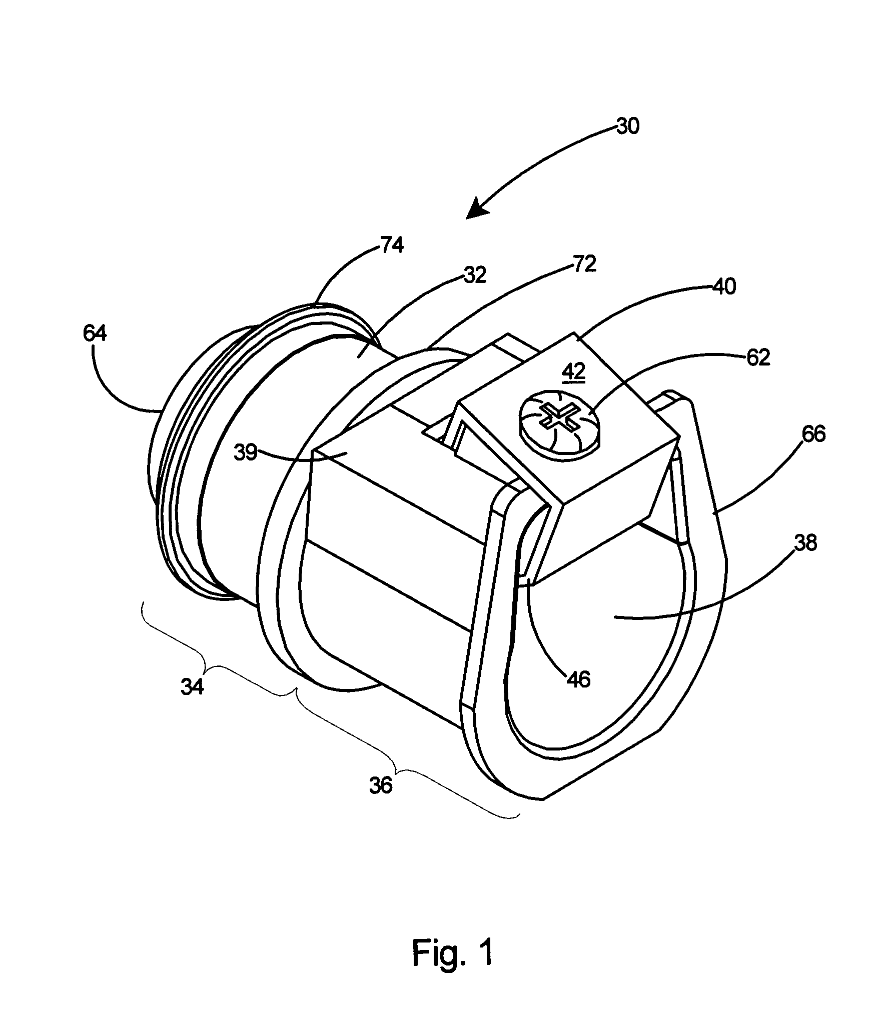
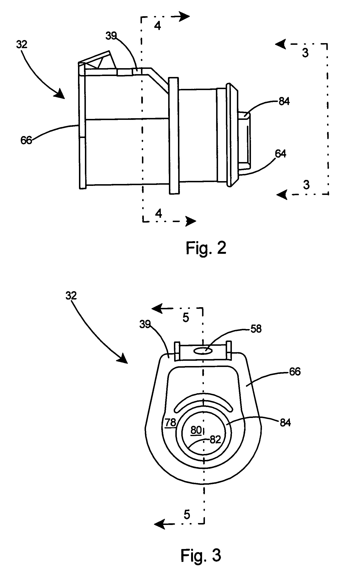
[0192]With reference to FIG. 1 there is shown a first embodiment of the present invention, an electrical fitting 30 having an improved arrangement for the securing of electrical cables thereto. The electrical fitting 30 includes a continuous tubular body 32 including a leading portion 34, a trailing portion 36, and a bore 38. A raised area 39 extends in one direction from the tubular body 32. Secured externally to the trailing portion 36 of the tubular body 32 is a clip member 40, with the clip member 40 including a base portion 42 at which it is secured to the tubular body 32.

[0193]Referring to FIG. 16, the bore 38 of the tubular body 32 includes a central axis 44 defined by the leading portion 34. The central axis 44 of the bore 38 is the axial center of the leading portion 34. A cylindrical volume 45 surrounds the central axis 44 within the leading portion 34. Within the raised area 39 of the trailing portion 36 is a cavity 47. The cavity 47 provides additional volume between the...


PUM


Abstract

A duplex electrical fitting having an improved arrangement on the trailing end for attaching electrical cables thereto. A connector body includes a leading opening, a midportion, two trailing openings, and a sidewall. Two open channels are provided in the sidewall on the trailing end of the connector, one open channel into each trailing opening. Each of the open channels extends from the trailing opening to the midportion of the connector body. Each of the channels includes a bridge adjacent the trailing opening which bridges each of the open channels. Each of the bridges is adapted to receive a tandem tang secured thereto. The tandem tangs include a common middle section and a leading tang and a trailing tang extending therefrom. Cable grabbing ends are provided on both the leading and trailing tangs. The leading and trailing tangs extend from outward of the connector body into the open channel. The tangs are of substantial length and are cantilevered over such a distance so as to enable easy insertion of cable within the trailing opening. The open channel permits additional space for flexing of the tangs of the tandem tang to further ease insertion of cables into the fitting. Bend lines on the leading and trailing tangs direct the cable grabbing ends toward an inserted cable and thereby hold the cable against the bottom of the open channel.

Description

[0001]This application is a Continuation-In-Part of U.S. patent application Ser. No. 11 / 300,859 filed Dec. 15, 2005 and still pending.FIELD OF THE INVENTION[0002]This invention relates to fittings for connecting electrical cables to a panel or an electrical box and specifically to a duplex electrical fitting having an improved arrangement on the trailing end for receiving electrical cables.BACKGROUND OF THE INVENTION[0003]Several prior art connectors have been proposed for the attachment of electrical cables to panels or electrical boxes. Some of these include a tubular body with a cavity on the trailing end and a split ring that is inserted within the cavity. Typically the split ring includes one or more cable gripping tangs for securing a cable to the trailing end of the connector. As a result of the limited space within the cavity, the length of the cable gripping tangs is limited. Thus the cable gripping tangs must be relatively short, making the tangs stiff and less flexible, w...

Claims


Application Information

Patent Timeline
Patent Type & Authority Patents(United States)
IPC IPC(8): H02G3/18
CPCH02G3/0666Y10T16/05
Inventor GRETZ, THOMAS J.
Owner ARLINGTON INDS
Why Eureka
Try Eureka