
Display device for aircraft and method for displaying detected threats

a technology for aircraft and detection threats, applied in navigation instruments, using reradiation, instruments, etc., can solve the problems of limiting the pilot's freedom of action in connection with decision-making, increasing fuel use, and not enough fuel for the planned mission

Inactive Publication Date: 2007-01-09
SAAB AB
View PDF12 Cites 20 Cited by
  • Summary
  • Abstract
  • Description
  • Claims
  • Application Information

AI Technical Summary

Benefits of technology

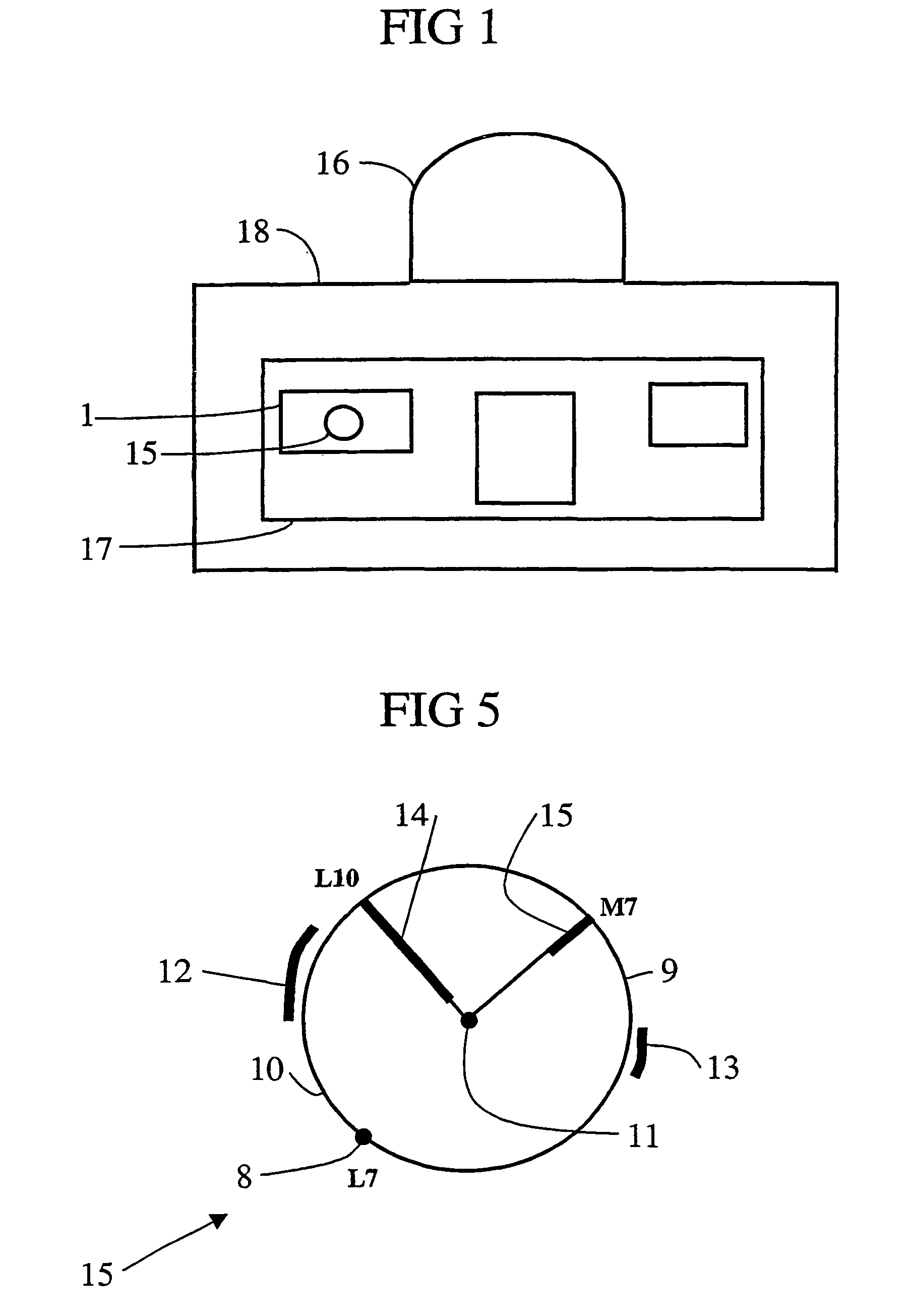
[0017]The aircraft is, e.g. a military airplane, primarily an attack or reconnaissance airplane. The planned mission may be a mission that has been planned in detail with breakpoints, and with precisely planned altitudes and speeds for each subsection between two breakpoints. The mission is thus divided into a number of continuous subsections that together form a polygon in which each section has its own associated altitude and speed. During the performance of a such a mission, the information presented by the display means is the very information that the pilot needs in order to make quick decision as to how he / she should act vis-a-vis the various problems that can arise in the form of the types of threats described above, or “internal” threats in the form of delays related to a timetable or shortage of fuel. The aforedescribed threats and internal threats are the factors that limit the pilot's freedom of action in connection with decision-making. These factors are also covariant. This means: that, for example, if the pilot increases speed to keep to the timetable, this will lead to increased fuel use, which could in turn mean that there will not be enough fuel for the planned mission, insofar as the fuel supply is not very good in relation to the mission. In another example where the pilot is planning to change the planned mission (replanning) by taking an alternate flight path to circumvent an external threat, the display device will provide the information that the pilot needs to make a quick and correct decision, i.e. the display device will indicate whether the timetable and fuel status permit such an evasive maneuver. It is thus extremely advantageous to display, along with directions to threats, the time until the threat, the time available to complete the mission in relation to the timetable, and the fuel status in relation to the planned mission.

Problems solved by technology

The aforedescribed threats and internal threats are the factors that limit the pilot's freedom of action in connection with decision-making.
This means: that, for example, if the pilot increases speed to keep to the timetable, this will lead to increased fuel use, which could in turn mean that there will not be enough fuel for the planned mission, insofar as the fuel supply is not very good in relation to the mission.

Method used


Image

  • Display device for aircraft and method for displaying detected threats
  • Display device for aircraft and method for displaying detected threats
  • Display device for aircraft and method for displaying detected threats

Examples


Embodiment Construction

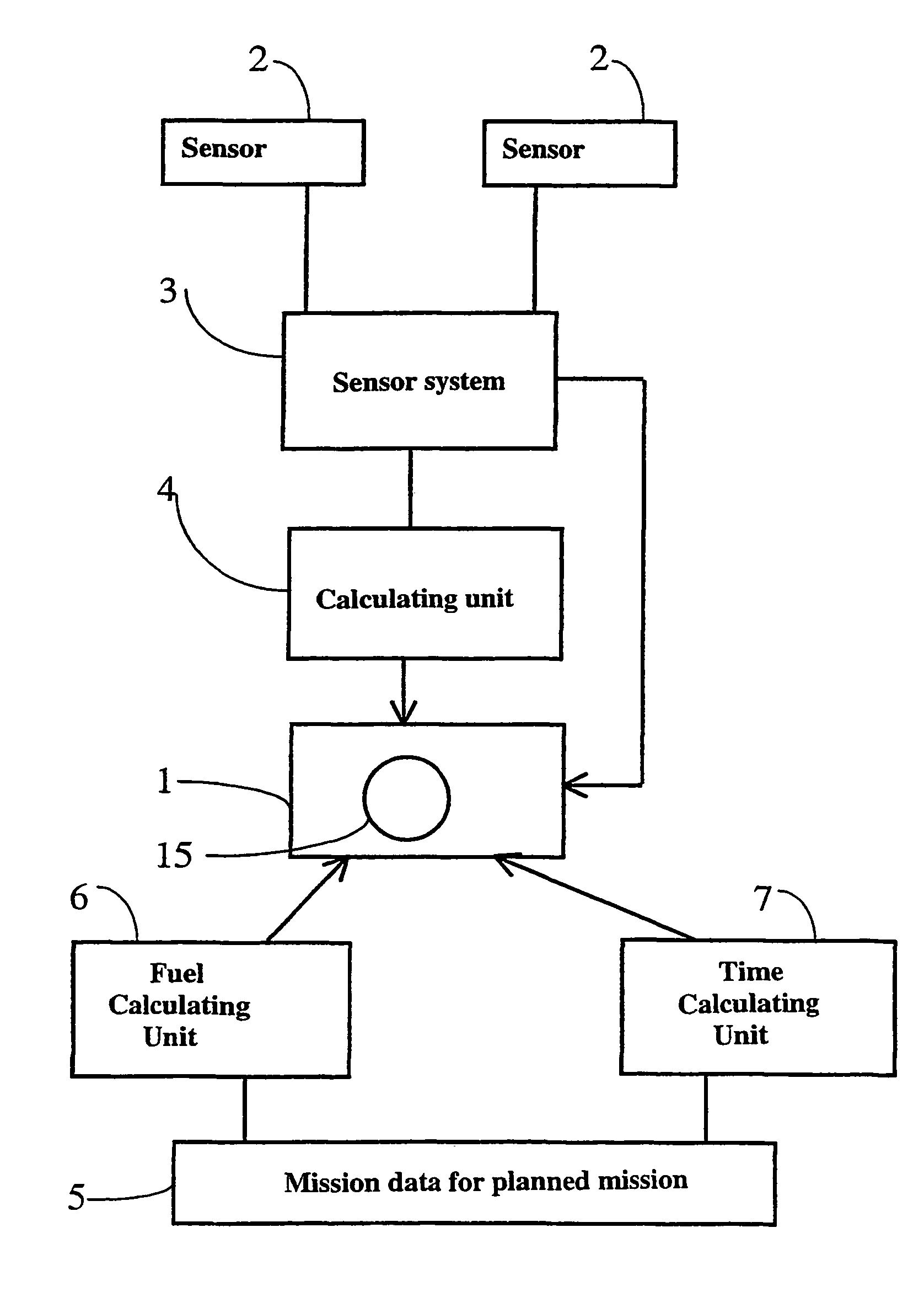
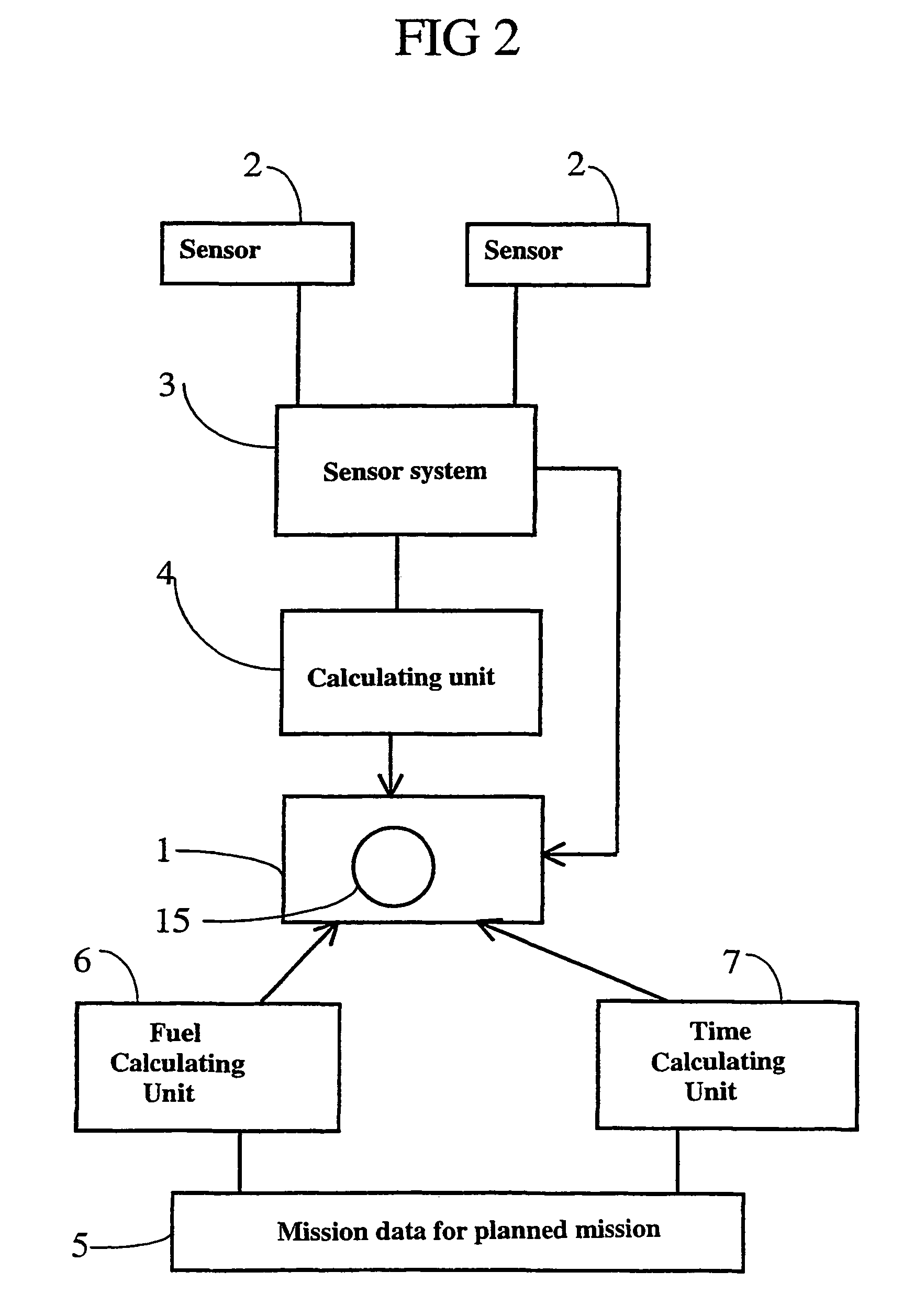
[0026]In FIG. 1, reference number 1 designates a device placed in a cockpit of, e.g. a military attack airplane. The device 1 has a display surfaced 15 realized using, e.g. LCD, CRT or VRD technology and installed, e.g. inside the front windshield of the cockpit in a so-called head-up 16, or in a so-called head-down display 17. In the embodiment shown in the figure, the head-down display 17 and the head-up display 16 have been installed in a panel 18, and the device 1 is included in the head-down display 17. The display surface 15 may alternatively be integrated with the airplane pilot's helmet (VRD technology). The device 1 is intended to display information via the display surface 15 for use as a decision-making aid during combat missions.

[0027]In FIG. 2, reference number 5 designates a unit in which a mission that has been planned in detail is input and stored with altitudes, positions and speeds for the entire mission precisely planned. The mission is divided into, e.g. a number...


PUM


Abstract

This invention concerns a display device for aircraft comprising a display surface (15) that has a punctual marking (11) arranged so as to represent the pilot's own airplane and one or more threat markings, each of which is arranged so as to represent a direction to an associated detected threat. The display device is characterized in that each threat marking comprise an indicator (14, 15) that contains information about the time to the associated threat, and in that it is arranged so as to present, on a display surface (15), a current time discrepancy relative to a planned mission and a remaining amount of fuel relative to the planned mission. The invention also concerns a method for presenting one or more detected threats in relation to an aircraft.

Description

TECHNICAL AREA[0001]This invention concerns a display device for aircraft according to the preamble to claim 1.[0002]The invention also concerns a method for displaying one or more detected threats in relation to an aircraft according to the preamble to claim 1.STATE OF THE ART[0003]Pilots of civil airplane have previously been dependent on to certain degree of visual contact with nearby airplanes, advice from ground-based traffic control stations to avoid collisions in the airspace, and on sensors (e.g. radar) carried in the airplane. However, systems exist today that include transponders that can be implemented in airplanes, and which can aid in the pilot in obtaining information concerning the positions of nearby passing airplane in relation to the pilot's own airplane. These transponders periodically send out query signals into the surrounding airspace. The transponders of nearby airplanes are arranged so as to respond to said query signals by emitting a response signal containi...

Claims


Application Information

Patent Timeline
Patent Type & Authority Patents(United States)
IPC IPC(8): G08G5/04G01C23/00G01S13/933
CPCG01C23/00G01S13/9303G01S13/933
Inventor ALFREDSSON, JENSROSENBLAD, TOMASSKINNARS, ORIAN
Owner SAAB AB
Learn More