Device and method for converting two-dimensional video to three-dimensional video

a technology of two-dimensional video and conversion image, which is applied in the direction of television system, instrument, color signal processing circuit, etc., can solve the problems of unnatural video obtained, increased distortion of the conversion image itself, and increased distortion of the conversion imag

Inactive Publication Date: 2007-01-09
SANYO ELECTRIC CO LTD
View PDF5 Cites 247 Cited by
  • Summary
  • Abstract
  • Description
  • Claims
  • Application Information

AI Technical Summary

Problems solved by technology

When the deformation is too large, an unnatural video is obtained.
(1) When the maximum projection amount Ymax′ is increased until the depth Yp is saturated, the distortion of the conversion image itself (the distortions of the R image itself and the L image itself) is increased in a portion having a depth in the vicinity of Ymax′.
(2) When an attempt to enlarge a dynamic range in a depth reproduction space is made, there is no alternative but to reduce the maximum recession amount Ymin′. Accordingly, an area projected forward from the screen is extremely reduced.
Therefore, it is no longer easy to say that the complete distance scale conversion is useful because complicated processing is performed.
Conversely speaking, a spatial distortion occurs on the screen.
However, it cannot be said that it is effective for the distance scale conversion.
Even in the polygonal line distance scale capable of controlling the projection amount ratio C, however, the maximum value h_dv_max [pixel] of the phase difference between the adjacent areas cannot be completely suppressed within the distortion allowable range h_supp_lev [pixel] (the principle of suppressing a distortion in a pixel scale cannot be faithfully realized).
On the other hand, a video which does not move or a video whose movement is complicated cannot be satisfactorily converted into a three-dimensional video.
Such a phenomenon that a stereoscopic effect of a conversion video greatly differs depending on an input video is inconvenient when a user adjusts a stereoscopic effect.

Method used


Image

  • Device and method for converting two-dimensional video to three-dimensional video
  • Device and method for converting two-dimensional video to three-dimensional video
  • Device and method for converting two-dimensional video to three-dimensional video

Examples


first embodiment

[1] Description of First Embodiment

[0096]Referring now to FIGS. 9 to 12, a first embodiment of the present invention will be described.

[0097]FIG. 9 shows the procedure for control in the CID method according to the first embodiment of the present invention.

[0098]First, one screen is divided into a plurality of areas, and information related to a high frequency and a contrast of luminance, and a chrominance (B-Y, R-Y) component are obtained from each of the areas (step 11). A depth estimate for each of the areas, which has been estimated from the information and a composition, is found (step 12). The found depth estimate is subjected to distance scale conversion and distortion suppression processing, thereby obtaining a target phase (step 13).

[0099]FIG. 10 shows the details of the distance scale conversion and distortion suppression processing at the step 13 shown in FIG. 9.

[0100]First, the depth estimate is subjected to the distance scale conversion in a dynamic range defined by Mfr...

second embodiment

[2] Description of Second Embodiment

[0120]Referring now to FIGS. 13 and 14, a second embodiment of the present invention will be described.

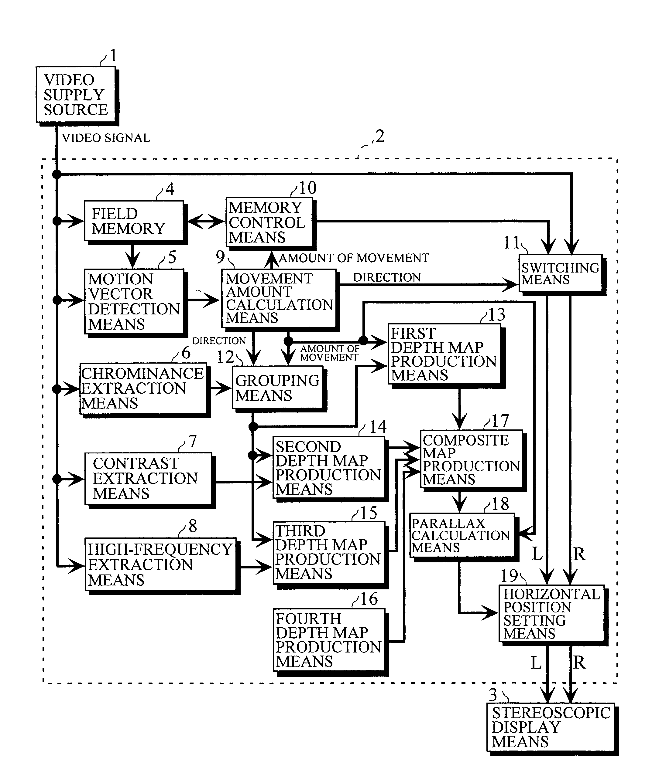
[0121]In FIG. 13, reference numeral 1 denotes a video supply source serving as video signal supply means such as a VTR (Video Table Recorder), a CD-ROM (Compact Disc Read-Only Memory), or TV broadcasting, reference numeral 2 denotes a 2D / 3D converting device for converting a two-dimensional video signal supplied from the video supply source 1 into a three-dimensional video signal, that is, a left eye video signal L and a right eye video signal R, and reference numeral 3 denotes stereoscopic display means using an image splitter system or the like for displaying the three-dimensional video signal outputted from the 2D / 3D converting device 2.

[0122]Description is made of the configuration of the 2D / 3D converting device 2.

[0123]Reference numeral 4 denotes a field memory storing as a video the video signal supplied from the video supply source 1 for e...

third embodiment

[3] Description of Third Embodiment

[0144]Referring now to FIGS. 15 and 23, a third embodiment of the present invention will be described.

[0145]FIG. 15 illustrates the configuration of a device for converting a two-dimensional video into a three-dimensional video (a 2D / 3D converting device).

[0146]In FIG. 15, reference numeral 101 denotes a video supply source serving as video signal supply means such as a VTR, a CD-ROM, or TV broadcasting, reference numeral 102 denotes a 2D / 3D converting device for converting the two-dimensional video signal supplied from the video supply source 1 into a three-dimensional video signal, that is, a left eye video signal L and a right eye video signal R, and reference numeral 103 denotes stereoscopic display means using an image splitter system or the like for displaying a three-dimensional video signal outputted from the 2D / 3D converting device 102.

[0147]Description is made of the configuration of the 2D / 3D converting device 102.

[0148]Reference numeral...


PUM


Abstract

There is provided parallax correction means for correcting a parallax for each area calculated by parallax calculation means in accordance with the magnitude of a motion vector for the area detected by motion vector detection means in order to prevent the three-dimensional effect of a conversion video from greatly differing depending on an input video when the MTD method and the CID method are simultaneously used.When a depth estimate is converted into a parallax, the depth estimate is subjected to distance scale conversion in order to suppress the distortion of the conversion image, to find a tentative target phase for each parallax calculation area, and a dynamic range in which a phase difference between the parallax calculation areas is within a distortion allowable range is searched for and is subjected to distance scale conversion, to find a tentative target phase, which operations are repeated.

Description

TECHNICAL FIELD[0001]The present invention relates to a device for and a method of converting a two-dimensional video into a three-dimensional video.BACKGROUND ART[0002]As a method of converting a two-dimensional video into a three-dimensional video, methods disclosed in JP-A-9-107562 and JP-A-10-51812 have been known.[0003]The outline of the method of converting a two-dimensional video into a three-dimensional video, which is disclosed in JP-A-9-107562, will be first described on the basis of FIG. 1.[0004]In a two-dimensional video (2D video), a state where a bird is flying from the left to the right in front of a mountain shall be picked up, as shown in images 1 to 5.[0005]A motion vector between images, for example, a motion vector in the case of transition from the image 1 to the image 2 or a motion vector for transition from the image 2 to the image 3, is extracted for each of a plurality of motion vector detection areas set in a screen. A subject (bird) area and a background (...

Claims


Application Information

Patent Timeline
Patent Type & Authority Patents(United States)
IPC IPC(8): H04N13/00
CPCH04N13/026H04N19/597G06T7/0051H04N13/0055H04N2013/0081H04N2013/0092H04N2013/0085G06T7/50H04N13/189H04N13/261
Inventor YAMASHITA, SYUGOMURATA, HARUHIKOIINUMA, TOSHIYANAKASHIMA, MITSUOMORI, TAKAYUKI
Owner SANYO ELECTRIC CO LTD
Why Eureka
Try Eureka