
Adaptive motion vector field coding

Inactive Publication Date: 2007-01-09
NOKIA TECHNOLOGLES OY
View PDF13 Cites 16 Cited by
  • Summary
  • Abstract
  • Description
  • Claims
  • Application Information

AI Technical Summary

Benefits of technology

[0022]By taking advantage of the predicted motion coefficients in a Motion Analyzer that forms part of the motion field coder of a video encoder, a better rate-distortion performance is achieved than with prior known solutions.

Problems solved by technology

Due to the very large number of pixels in the frame, it is not efficient to transmit a separate motion vector for each pixel.
Therefore, it is not efficient to always use all N+M motion coefficients per segment.
However, the prediction error tends to increases, as the motion field model becomes coarser.
Usually such terminals have limited space for additional components and operate by a battery so that they are likely not accommodate computing capacity comparable to fixed devices such as desktop computers.
The main disadvantage of these methods is their high computational complexity and the small number of different motion field models that can be tested in practice.
After each removing step, the squared prediction error is calculated and removing is continued until the magnitude of the error is not acceptable.

Method used


Image

  • Adaptive motion vector field coding
  • Adaptive motion vector field coding
  • Adaptive motion vector field coding

Examples


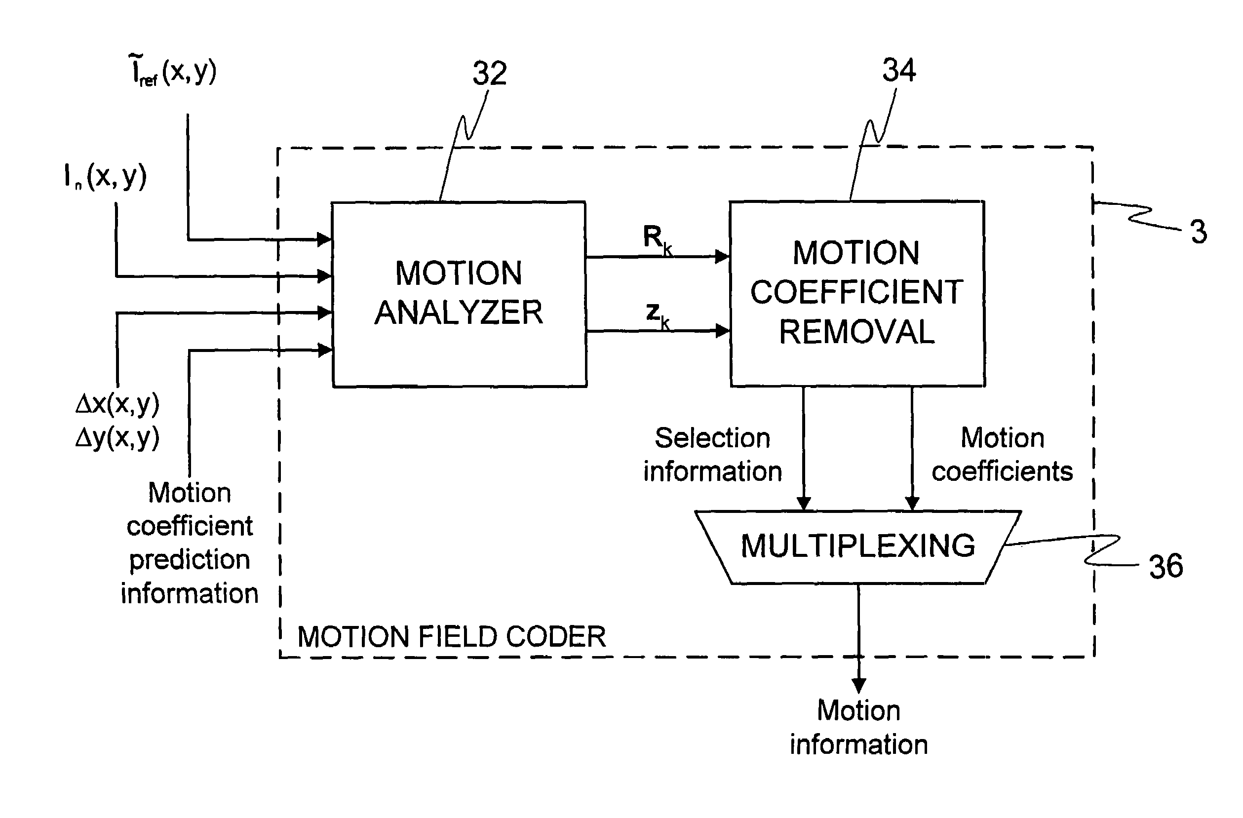
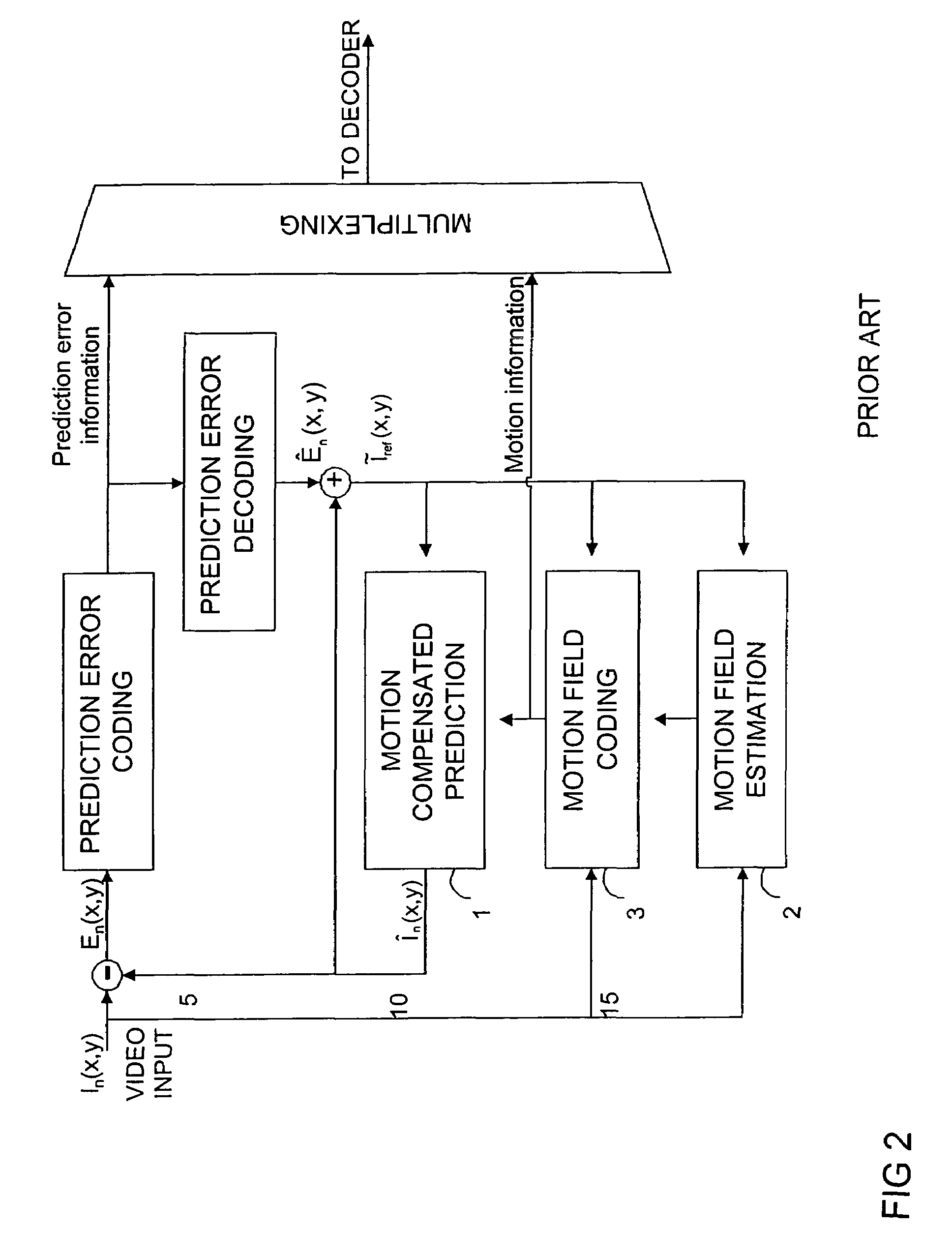
Embodiment Construction

[0031]FIGS. 1 to 3 are described above.

[0032]In the following, an overview of the invention is provided to facilitate the further description of various embodiments of the invention.

[0033]In accordance with a preferred embodiment of the invention, the motion field coder of a video encoder comprises two main blocks.

[0034]The first main block is called a Motion Analyzer 32, FIGS. 4 and 5. Its task is to find a new representation of the inputted motion field produced by the motion field estimation block 2, FIG. 2. This new representation is applied to the second main block, a motion coefficient removal block 34, FIG. 4. Operations in the Motion Analyzer include a plurality of steps comprising matrix operations: In the first step the prediction frame's dependency on motion vectors is linearized using an approximation method. In the second step, a matrix Ak and a vector dk are constructed for minimization of the square prediction error. In the third step, a diagonal system of linear equa...


PUM


Abstract

A method for motion compensated encoding of video data.The method comprises the steps of:generating a motion vector field of video pixels of a current frame to be coded based on a reference frame;obtaining segmenting information defining the division of the current frame into image segments;coding the motion vector field of an image segment Sk to provide compressed motion information comprising a motion coefficient vector ck comprising a set of motion coefficients ci, such that ci·fi(x,y) represents the motion vector field, whereby fi(x,y) defines a certain set of basis functions, wherein i is an index defining a correspondence between each basis function and a corresponding motion coefficient;predicting a motion vector field of a subsequent image segment SL with a set of predicted motion coefficients pi based upon the previously generated motion coefficient vector ck;generating for the subsequent segment SL a set of refinement motion coefficients ri corresponding to the difference between the set of motion coefficients ci and a set of predicted motion coefficients pi such that pi+ri=ci.Another aspects of the invention comprise corresponding video codec, mobile station, telecommunications network and computer program product.

Description

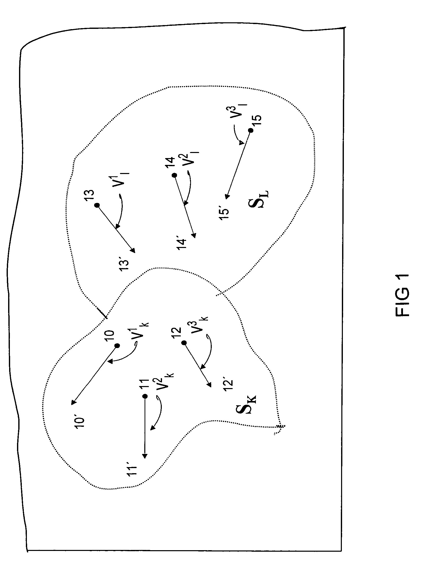
CROSS-REFERENCE TO RELATED APPLICATION[0001]This Application is a continuation of U.S. patent application Ser. No. 09 / 371,641 filed on 11 Aug. 1999 now U.S. Pat. No. 6,735,249, which is a continuation of U.S. patent application Ser No. 09 / 489,327 filed on 21 Jan. 2000.FIELD OF THE INVENTION[0002]The present invention relates to video compression. In particular, the invention relates to coding of an estimated motion field and to generating motion information in a video sequence.BACKGROUND OF THE INVENTION[0003]Motion compensated prediction is a key element of the majority of video coding schemes. To describe the operation of motion compensated prediction it should be appreciated that each digital image contains certain set of pixels corresponding to certain parts of the image. Each pixel may be represented, for example, as intensities of Red, Green and Blue (RGB color system) or as intensities of the luminance and two chrominance components.[0004]FIG. 1 shows illustratively two segme...

Claims


Application Information

Patent Timeline
IPC IPC(8): H04B1/66H03M7/36H04N7/32H04N7/26
CPCH04N19/147H04N19/46H04N19/517H04N19/543H04N19/567H04N19/19
Inventor LAINEMA, JANIKARCZEWICZ, MARTA
Owner NOKIA TECHNOLOGLES OY
Learn More