Guiding movement of capless filler neck closure

a technology of filler neck and guide rod, which is applied in the direction of liquid handling, refuse gathering, packaging goods type, etc., can solve the problems that the filler cap has proven to be a source of trouble, and achieve the effect of eliminating scrubbing and facilitating a positive seal

Inactive Publication Date: 2007-01-16
EATON CORP
View PDF11 Cites 53 Cited by
  • Summary
  • Abstract
  • Description
  • Claims
  • Application Information

AI Technical Summary

Benefits of technology

[0006]The present invention provides a capless filler neck of the type having a nozzle-receiving aperture provided in a bulkhead on the end of the filler neck. The invention employs a closure or door with a resilient seal and is biased to seat about the nozzle aperture on the downstream side of the bulkhead. The closure or door is moveably disposed on a support structure which may be attached as a sub-assembly to the downstream side of the bulkhead and which permits the closure or door, upon operator insertion of a refueling nozzle through the aperture, to be moved a short distance in translation to remove the door seal from the seat. Upon further insertion of the nozzle, movement of the closure is guided, by engagement of following surfaces provided on the door with a set of guide surfaces on the support structure, to move pivotally out of the way to a position substantially not obstructing the aperture and permitting full insertion of the nozzle. The guide surfaces on the support structure in one embodiment comprise a pair of spaced tracks in the form of slots; and, the following surfaces on the door comprise a pair of trunnion pins or axles. Upon removal of the nozzle, the door is biased to reverse the sequence of movement and permits the seal to move against the nozzle aperture on the downstream side of the bulkhead during translation movement of the door to thereby facilitate a positive seal between the door and the aperture and eliminate scrubbing of the seal which would otherwise occur if the door were simply hinged.

Problems solved by technology

However, if a fault is detected in the system, an indicator for the operator is energized.
Inasmuch as fuel tank filler caps are removed and repositioned many times by the vehicle operator over the service life of the vehicle, the filler cap has proven to be a source of trouble and often leakage due to wear or improper positioning by the vehicle operator; and, thus the on-board diagnostic system will indicate a fault in the integrity of the vapor containment in the fuel system.
Providing an automatic capless sealing closure for a fuel tank filler neck has proven to be a real challenge inasmuch as the closure must withstand not only the inertial loads imposed by vehicle bounce and jounce, but must also maintain the integrity of the filler neck closure seal in the event of a collision and / or vehicle rollover.

Method used


Image

  • Guiding movement of capless filler neck closure
  • Guiding movement of capless filler neck closure
  • Guiding movement of capless filler neck closure

Examples


Embodiment Construction

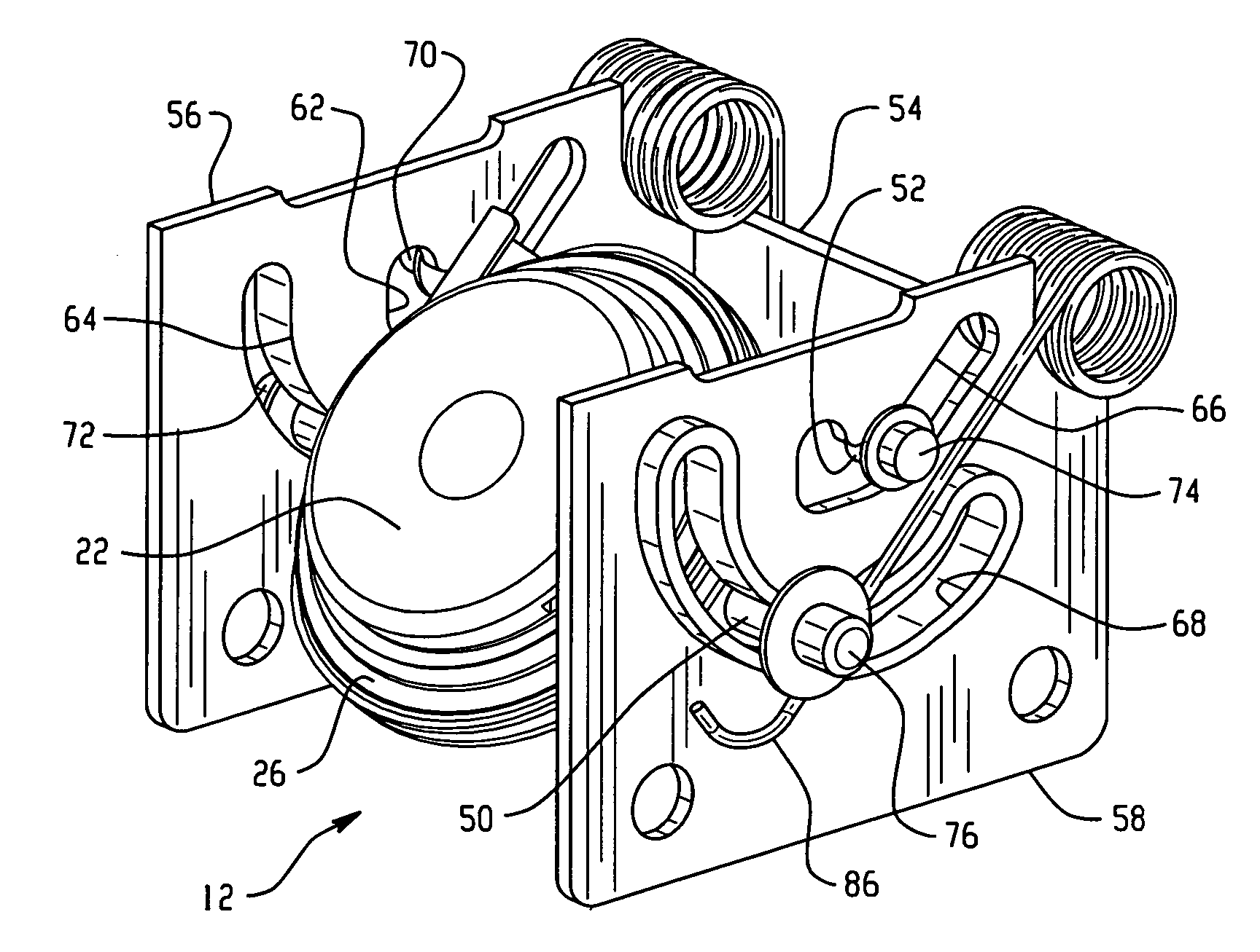
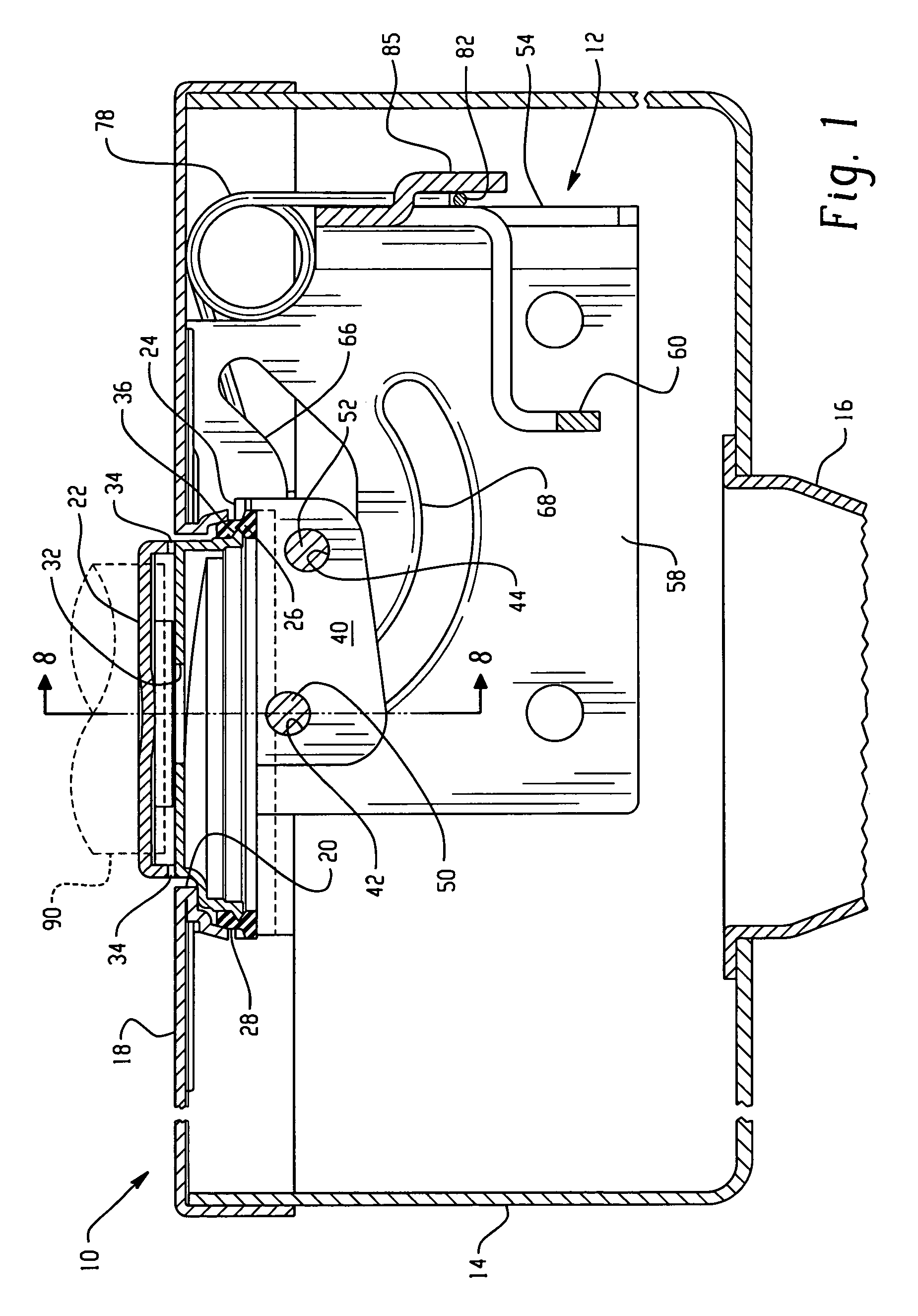
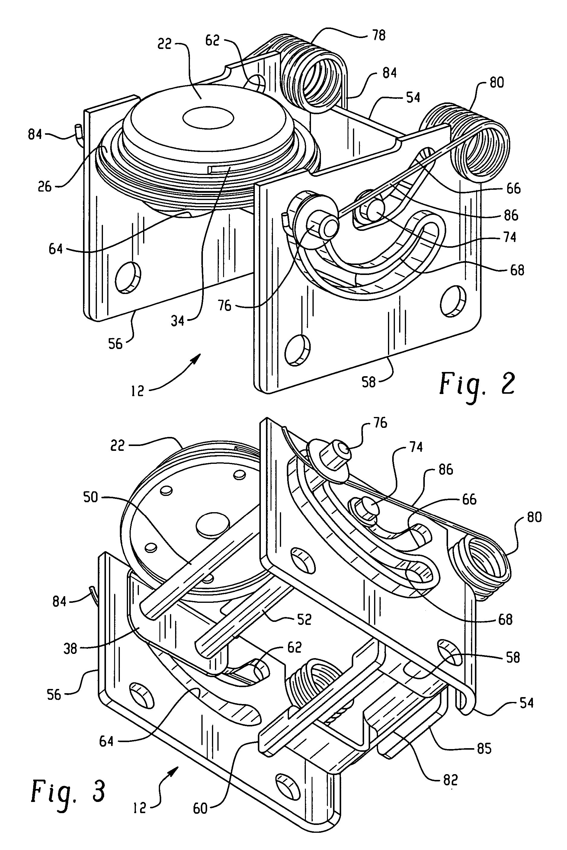
[0015]Referring to FIG. 1, a fuel tank filler tube assembly embodying the present invention is indicated generally at 10 wherein a capless closure and support structure are indicated as a subassembly generally at 12 as received in a filler cup 14 attached to the upper end of the filler tube or neck 16. The filler cup 14 has a bulkhead 18 secured and sealed over the open end thereof, which bulkhead has a nozzle-receiving aperture 20 formed therein.

[0016]In the illustrated exemplary embodiment a closure door 22 is shown with a radially outwardly extending peripheral flange 24 formed thereon which has a plurality of apertures 28 therethrough which may be spaced circumferentially thereabout. A flexible annular seal 26 is disposed about the flange and secured thereto; as, for example, by insert molding the seal 26 thereon with portions of the molded seal material passing through the apertures 28. The door 22 may include a one-way pressure relief valve (not shown) which opens to permit fl...


PUM

PropertyMeasurementUnit
flexibleaaaaaaaaaa
pressureaaaaaaaaaa
volumeaaaaaaaaaa

Abstract

A capless filler tube closure door has a pair of spaced axles or pins which are guided by slots to initially upon being opened by a refueling nozzle move in translation away from the nozzle orifice seat and then pivot out of the way so as not to obstruct the nozzle. Upon nozzle removal as the door approaches the seat, it moves in linear translation to close on the seat to ensure uniform sealing.

Description

BACKGROUND OF THE INVENTION[0001]The present invention relates to filler tubes for fuel tanks for motor vehicles and more particularly to the closure for the refueling nozzle receiving end of the filler tube or neck as it is commonly referred to.[0002]Recent mandated requirements for limiting fuel vapor emission to the atmosphere from motor vehicle fuel tanks and fuel supply systems have required an on-board diagnostic system which monitors the integrity of the fuel system at selected intervals during operation to determine if vapor leaks are present in the system. Typically, such on-board diagnostics utilize electrically controlled valves in the vapor vent lines to permit the engine air inlet or induction system to draw a slight vacuum in the system and measure the leak rate of the system as a function of the change in the vacuum over a selected time interval. Alternatively a slight positive or gage pressure may be employed to detect leakage. Currently, production motor vehicles ar...

Claims


Application Information

Patent Timeline
Patent Type & Authority Patents(United States)
IPC IPC(8): B65B1/04
CPCB60K15/0406Y10S220/33B60K2015/0429B60K15/04
Inventor WALKOWSKI, PAUL D.
Owner EATON CORP
Why Eureka
Try Eureka