Apparatus and method for supporting structures on offshore platforms

a technology for supporting structures and offshore platforms, applied in special purpose vessels, sealing/packing, borehole/well accessories, etc., can solve the problems of high cost of day rental for floatable drilling rigs, high cost of exploration, drilling, completion and production in these deep waters, and achieve the effect of performing coiled tubing well work safely

Active Publication Date: 2007-01-16
DEVIN INT
View PDF9 Cites 20 Cited by
  • Summary
  • Abstract
  • Description
  • Claims
  • Application Information

AI Technical Summary

Benefits of technology

[0015]An advantage of the present invention is that the system and method can be used on floating platforms. Another advantage is that the system and method provides for motion compensation on a well undergoing well intervention and remedial well work. Yet another advantage is that the apparatus can be used with other motion compensation devices such as the apparatus disclosed in U.S. patent application Ser. No. 10 / 736,267 entitled “Motion Compensation System and Method”, filed 15 Dec. 2003, which is incorporated herein by express reference. Still yet another advantage is that the present invention allows for performing coiled tubing well work safely.
[0016]A feature of the present application is the use of a sliding frame assembly that allows the lateral movement of an attached structure relative to the apparatus. Another feature is the x-axis frame that supports an injector head on a floating platform, and wherein the x-axis frame pivots along the x-axis. Still yet another feature is the z-axis frame that supports an injector head on a floating platform, and wherein the z-axis frame pivots along the z-axis.
[0017]Another feature includes the modular design of the components. The modularity allows for ease of transportation, delivery and rig up. Yet another feature includes the ability to use the apparatus with a track stack, and wherein the track stack can be used to build the height needed on specific well applications by simply stacking spacers one on top of the other.
[0018]Another feature is that motion compensation is provided in the vertical direction and horizontal direction as well as along the x and z axis. Yet another feature is biasing means that restricts and controls the amount of pivoting of the z-axis frame and the x-axis frame. Still another feature is the use of an adapter frame that is part of the apparatus and connects to the injector head.

Problems solved by technology

In deep water, a fixed leg type of platform is generally not an option due to the extreme water depths.
The exploration, drilling, completion and production in these deep waters is very expensive.
For instance, day rental rates for floatable drilling rigs can cost over $300,000 per day in some instances.
Wave conditions may cause a cyclic buoyant force on these floating platforms based on the raising, lowering, heaving and pitching of the platform.
Moreover, tidal conditions may cause a variation in platform height and cause similar buoyant forces.
While an operator is in the midst of performing well work, the motion of the platform can have detrimental effects on the equipment and ongoing operations.
This motion could potentially cause serious damage such as breaking the connection of the coiled tubing to the riser which in turn could lead to a catastrophic failure.
As readily understood by those of ordinary skill in the art, numerous operational problems may be encountered before, during and after the well intervention work.
However, due to the various movements being experienced by the floating platform, alignment of the equipment is difficult.
A significant amount of time must be spent in rigging up equipment, which equates to significant sums of money due to the day rates of the rig.

Method used


Image

  • Apparatus and method for supporting structures on offshore platforms
  • Apparatus and method for supporting structures on offshore platforms
  • Apparatus and method for supporting structures on offshore platforms

Examples


Embodiment Construction

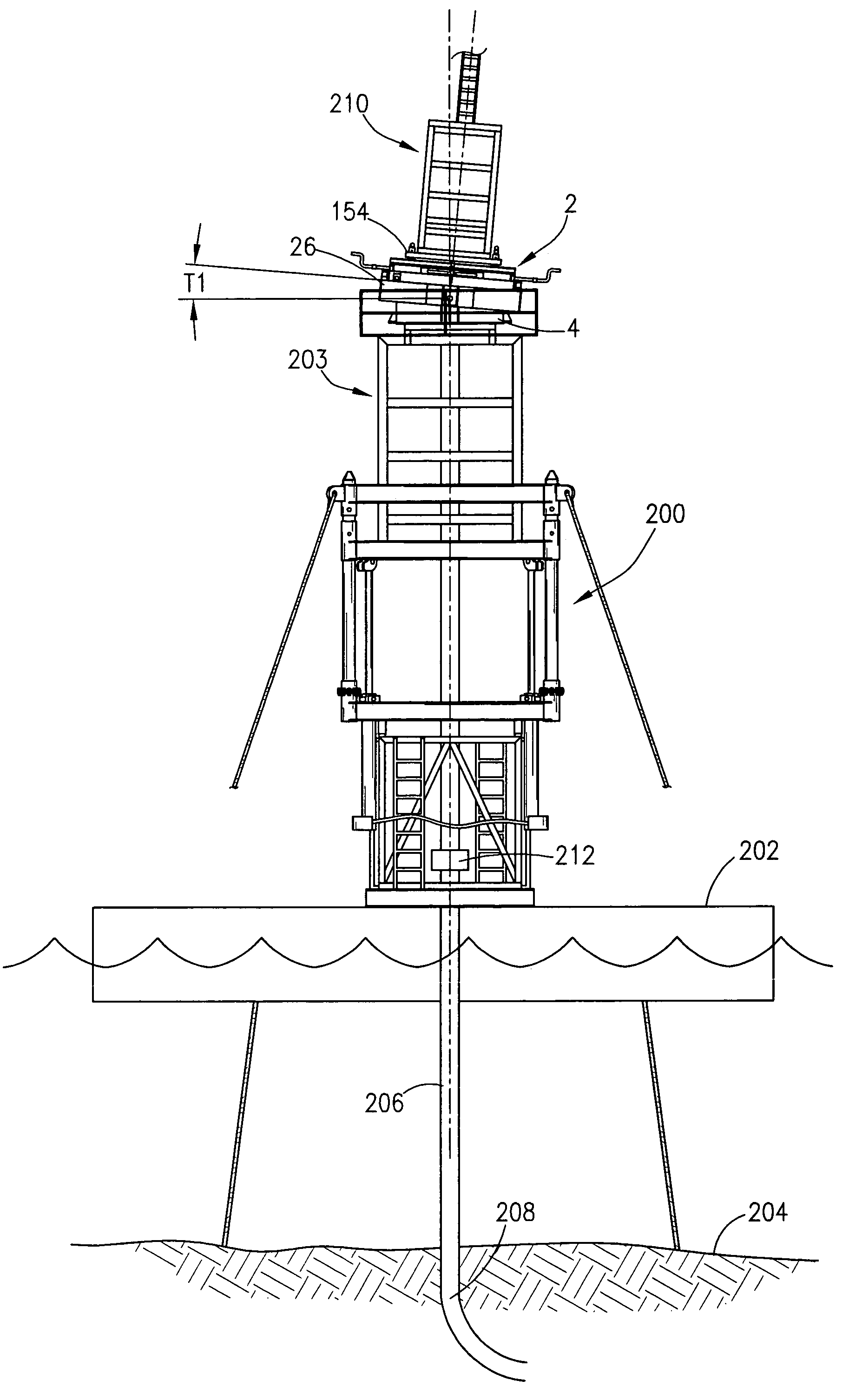
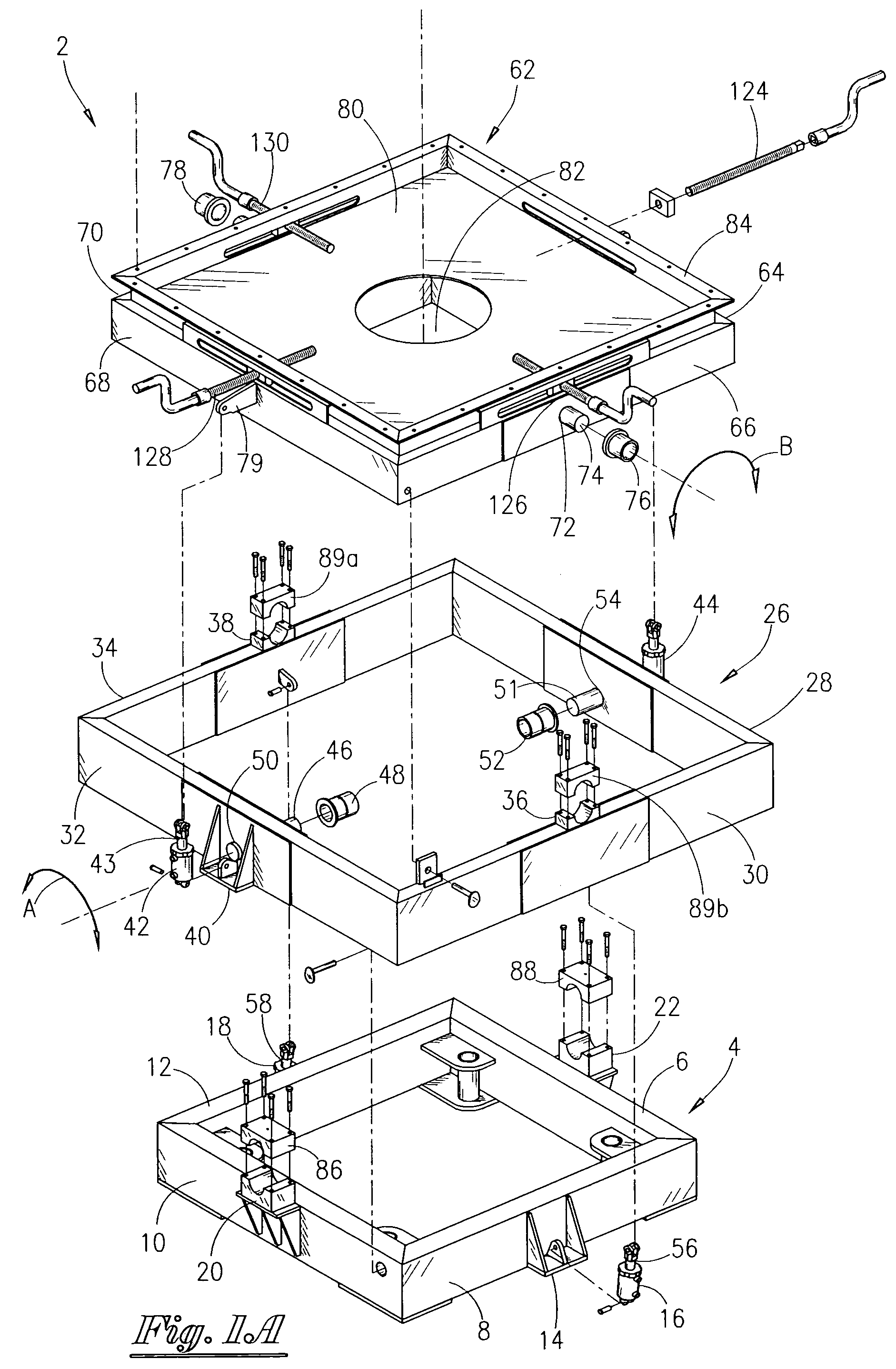
[0029]Referring now to FIG. 1A, an exploded isometric view of the apparatus 2 of the preferred embodiment of the present invention will now be described. The apparatus 2 contains a base frame 4, wherein the base frame 4 is generally rectangular having a first side 6, second side 8, third side 10, and fourth side 12. In the most preferred embodiment, the sides are of equal length so that the base frame is a square. The side 8 has a cylinder bracket 14 that will have operatively associated therewith the cylinder means 16. The side 12 has a cylinder bracket (not seen in this view) that will have operatively associated therewith the cylinder 18. The base frame 4 will also contain a first cradle 20 attached to the side 10, and a second cradle 22 attached to the side 6. As will be explained in greater detail later in the application, the base frame 4 is attached to the deck of a floating platform, such as a floating drilling rig.

[0030]The apparatus 2 further contains an x-axis frame 26 an...


PUM


Abstract

An apparatus for supporting a structure on a platform. The platform may be a floating platform. The apparatus comprises a base frame, wherein the base frame has a first bracket and a second bracket attached thereto. The apparatus further includes a x-axis frame having a first pivot point and a second pivot point. The apparatus further comprises a z-axis frame having a third pivot point and a fourth pivot point. A sliding frame assembly is operatively positioned within the z-axis frame, and wherein the sliding frame assembly has a plurality of rods for connecting with an injector head. The apparatus may further include a motion restriction system that restricts movement of the x-axis frame and the z-axis frame. The sliding frame assembly comprises a sliding pad for lateral movement. A method for compensating for the movement of a floating platform having a riser extending therefrom is also disclosed.

Description

BACKGROUND OF THE INVENTION[0001]This invention relates to a structure for supporting structures on offshore platforms. More particularly, but not by way of limitation, this invention relates to a structure and method for supporting and compensating for movement during well intervention operations on offshore platforms.[0002]Hydrocarbons are located in subterranean reservoirs. The search for hydrocarbons has brought operators to remote and exotic areas of the globe. Deep water tracts have been explored and drilled with increasing frequency in recent years. Platforms set in waters of 1,000 to 2,000 feet have become common place, and in some instances, wells have been drilled in water depths of over 5,000 feet. Different types of drilling and production platforms have been used in these deep waters. One type of platform is a tension leg platform (TLP). In the TLP, a floating platform is connected to the ocean floor via tendons such as steel cables, as is well understood by those of or...

Claims


Application Information

Patent Timeline
Patent Type & Authority Patents(United States)
IPC IPC(8): E21B7/12E21B19/22E21B29/12
CPCE21B19/22
Inventor MONCUS, JAMES DEVINMILLER, JR., JOSEPH HAYDEN
Owner DEVIN INT
Why Eureka
Try Eureka