
Safety anchoring device comprising a shock absorber

a safety anchoring and shock absorption technology, applied in the field of anchoring safety, can solve the problems of not having the strength of the receiving structure to withstand large forces, adding significantly to the cost of work undertaken, and not having the resistance to forces, so as to achieve the effect of extra cos

Inactive Publication Date: 2007-01-16
VERTIC
View PDF22 Cites 40 Cited by
  • Summary
  • Abstract
  • Description
  • Claims
  • Application Information

AI Technical Summary

Benefits of technology

[0012]The aim of the present invention is to produce an anchoring device whose reliability may be verified without extra cost and which, where appropriate, may be reused with a minimum amount of repair either for additional tests or for fastening to a roof.
[0014]Another aim of the present invention is to produce an anchoring device whose reliability in terms of fastening or whose use is not compromised when the profile of the roof covering changes.
[0015]An additional aim of the present invention is directed toward providing anchoring safety in spite of a roof covering on which the anchoring device is fastened having a low resistance to forces.

Problems solved by technology

In certain cases, the receiving structure does not have sufficient strength to withstand large forces, such as during a fall, for example.
This problem arises in particular in the case of anchoring devices fastened directly to the framework and passing through the roof covering.
The fact that the sealing function of the roof covering has to be restored after the anchoring device has been installed obviously adds significantly to the cost of the work undertaken.
Fastening anchoring devices directly to the roof covering presents not only problems of resistance to forces but also problems connected with variable forms of the roof coverings.
Developing such anchoring devices is very difficult and requires a high number of tests for each intended use.
It may be difficult to be able to reconcile the parameters and the tests do not generally allow verification to be carried out without irreversibly damaging the anchoring device.

Method used


Image

  • Safety anchoring device comprising a shock absorber
  • Safety anchoring device comprising a shock absorber
  • Safety anchoring device comprising a shock absorber

Examples


Embodiment Construction

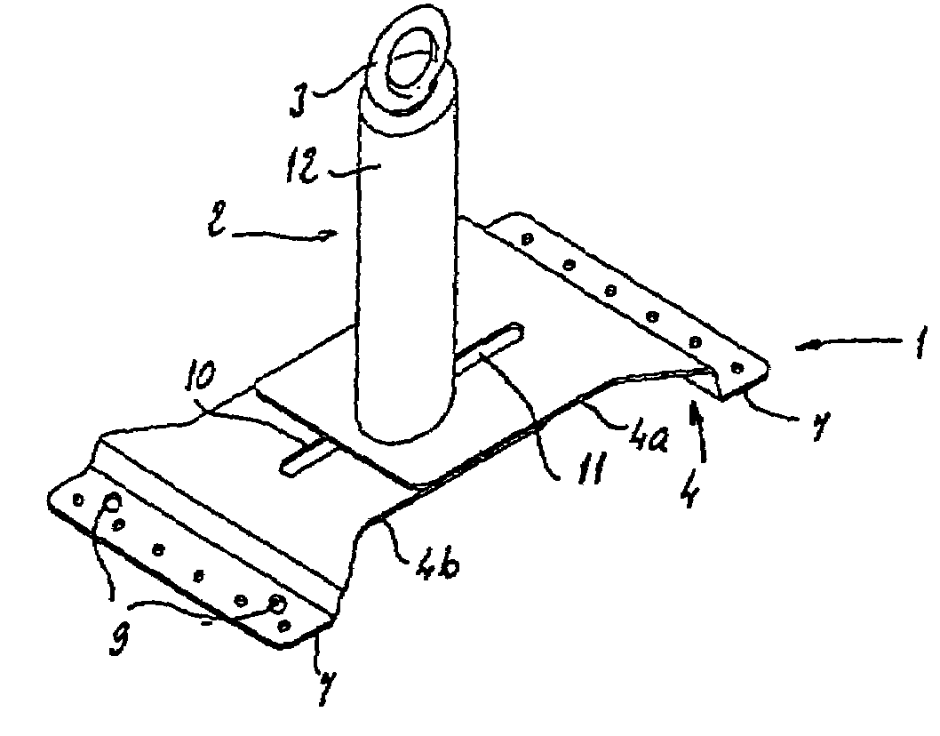
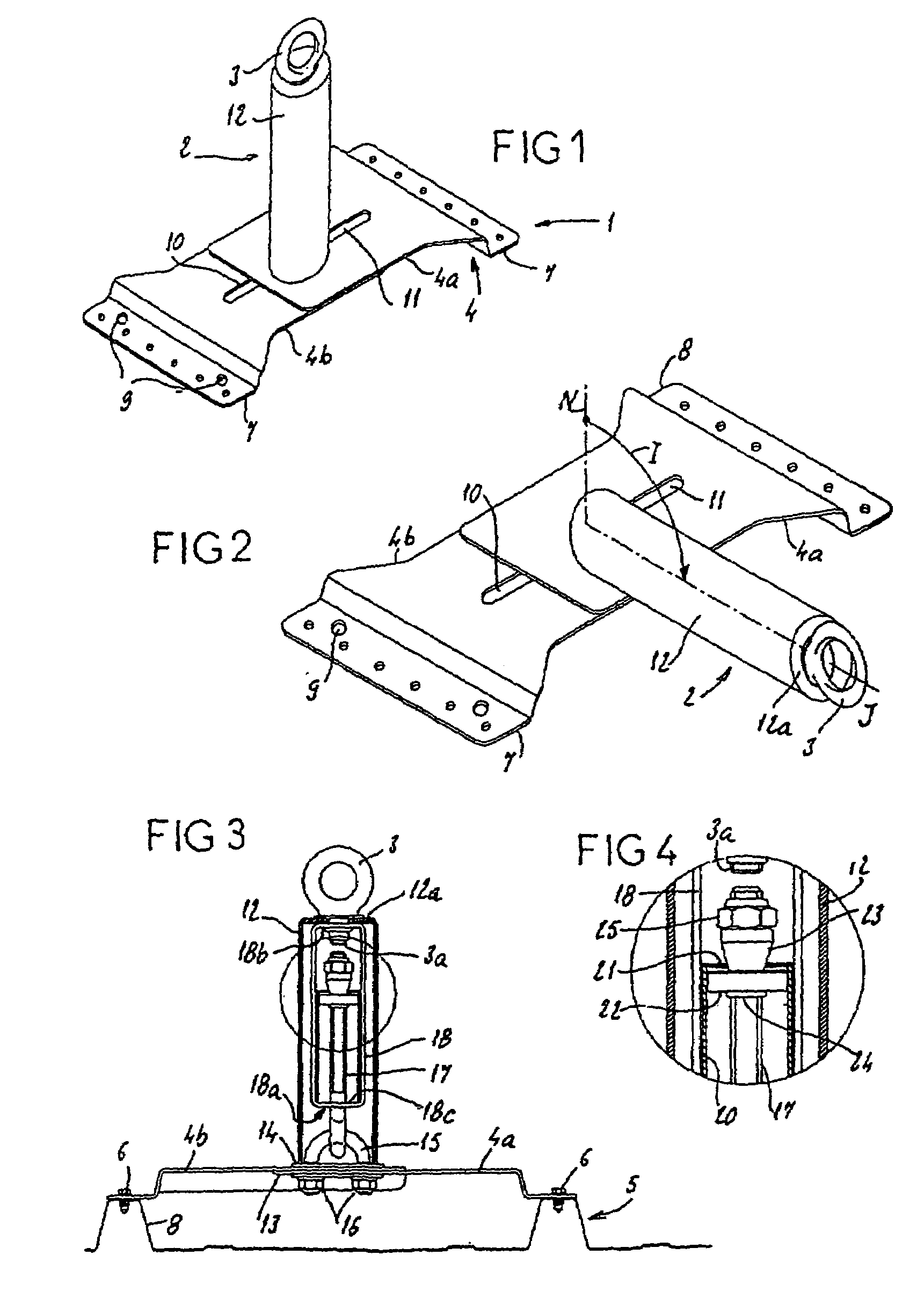
[0041]FIG. 1 shows an exemplary embodiment of an anchoring device 1 according to the invention.

[0042]The anchoring device 1 comprises a hitching element 2 surmounted by a hitching ring 3.

[0043]The anchoring device 1 also comprises a base 4 intended to be fastened to a roof covering 5. Means for mounting the hitching element 2 on the base 4 are also provided.

[0044]The base 4 is intended to be fastened to the roof covering 5 using fastening means 6 of the self-drilling screw type that respectively pass through a supporting end 7 of the base 4 in order to be screwed, for example, into a ridge 8 of the roof covering 5, as depicted in FIG. 3, for example. The base 4 is provided with drilled holes 9 for this purpose. These are made in the supporting end 7 of the base 4, for example.

[0045]The base 4 is made up of two partially superimposed parts 4a, 4b that are able to slide relative to one another for adjustment purposes. Each of the parts 4a, 4b is provided with an oblong hole 10, 11 mad...


PUM


Abstract

The invention relates to An anchoring device that is intended for, for example, the roof of a building. The inventive device comprises: a base which is used to fix to roofing; a hook element which is mounted to the base at one end thereof and which comprises a hook ring at the other end; a tilting mechanism which, in the event of an impact, enables the hook element to tilt in a normal plane in relation to the plane of extension of the base; a damping mechanism which is used to absorb energy during the tilting of the hook element. The damping mechanism comprises a trigger mechanism that can be used to prevent the hook element from tilting when the element is subjected to a force having an intensity that is lower than a pre-determined threshold. The aforementioned trigger mechanism comprises a removable part which is different from the other elements making up the damping mechanism.

Description

BACKGROUND OF THE INVENTION[0001]This application is a 371 of PCT / FR02 / 03454, filed Oct. 10, 2002[0002]The present invention relates to the field of anchoring safety, for example for people working high up on roofs of buildings or on other structures.[0003]To ensure the safety of individuals, in particular those working on roofs, the worker is provided with a harness and a tie that he connects to an anchoring device. In the event of a fall, it is this anchoring device, fastened to a receiving structure, for example the roof, which checks the fall.[0004]Such an anchoring device must be able to limit the height of a person's fall as far as possible and induce a minimum amount of force on the receiving structure.[0005]In certain cases, the receiving structure does not have sufficient strength to withstand large forces, such as during a fall, for example. It is therefore essential in those cases for the anchoring device to have an energy-absorbing capability, operating as it were as a s...

Claims


Application Information

Patent Timeline
IPC IPC(8): E04G5/14E04G3/26E04H17/22A62B35/04E04G21/32
CPCA62B35/04E04G21/3261Y10S256/06E04G21/3276E04G21/329
Inventor ARGOUD, RODOLPHE
Owner VERTIC
Features
  • Generate Ideas
  • Intellectual Property
  • Life Sciences
  • Materials
  • Tech Scout
  • Unparalleled Data Quality
  • Higher Quality Content
  • 60% Fewer Hallucinations
Learn More