Seat rail for aircraft cabin and method of manufacturing such a rail

a seat rail and aircraft cabin technology, applied in the direction of seating arrangements, furniture parts, machine supports, etc., can solve the problems of high installation time and cost of these assemblies, particularly restrictive mass of attachment assemblies, and extreme disadvantage in terms of associated mass, so as to reduce the number of components and simplify the design of attachment assemblies , the effect of cost and mass and installation tim

Active Publication Date: 2007-01-16
AIRBUS OPERATIONS (SAS)
View PDF17 Cites 36 Cited by
  • Summary
  • Abstract
  • Description
  • Claims
  • Application Information

AI Technical Summary

Benefits of technology

[0016]Furthermore, the rail web is not intended to be fitted with parts belonging to attachment assemblies, consequently fish plating operations are easier.
[0017]Moreover, the fact that the connection devices are made in a single piece with the web and top and bottom flanges reduces the installation time of the rail on the aircraft structure, and also limits the number of parts affected by galvanic corrosion.
[0018]Furthermore, this embodiment in which the seat rail is in a single piece advantageously implies that when the connection devices are approximately in line with the web, the forces passing through these connection devices then propagate directly into the web of the rail, without any risk of deforming the free lateral ends of the bottom flange.
[0019]Preferably, each connection device is a tenon, for example designed to cooperate with a clevis of an attachment assembly connecting the rail to the aircraft structure, or a clevis, for example intended to cooperate with a tenon in such an attachment assembly. In both proposed cases, the simple installation of a pin passing through the tenon and the clevis mentioned above advantageously provides a mechanical connection between the rail and the connecting rod of a given attachment assembly.

Problems solved by technology

Although this solution does enable satisfactory installation of the rail on the aircraft structure, the associated attachment assembly for each anchor point on the rail includes a very large number of parts which is extremely disadvantageous in terms of the associated mass.
In this respect, note that the above-mentioned disadvantage related to the mass of attachment assemblies is particularly restrictive because the number of anchor parts on aircraft may be extremely high, for example more than two hundred.
Furthermore, the large number of parts required to make up attachment assemblies also has disadvantages such that the installation time and costs of these assemblies are very high.
Furthermore, the many metallic parts in contact are naturally subject to galvanic corrosion.
This then makes it necessary to apply protecting layers during assembly, which further increase the rail installation time on the aircraft structure.
It is obvious that the parts of the attachment assembly located at the web of a rail end significantly complicate fish plating applied onto an adjacent rail.

Method used


Image

  • Seat rail for aircraft cabin and method of manufacturing such a rail
  • Seat rail for aircraft cabin and method of manufacturing such a rail
  • Seat rail for aircraft cabin and method of manufacturing such a rail

Examples


Embodiment Construction

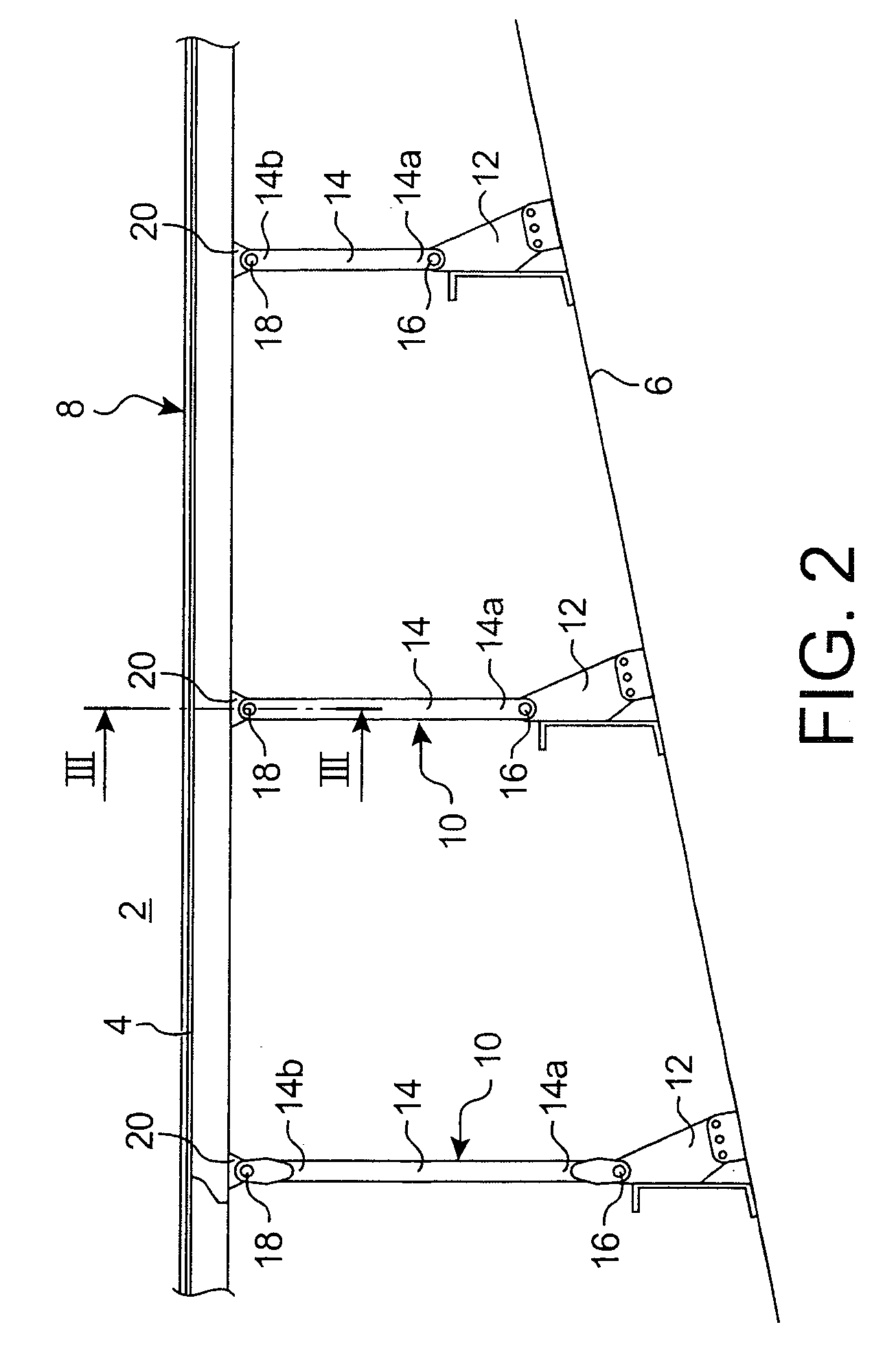
[0035]With reference to FIG. 2, the figure briefly shows part of an aircraft (not referenced) including a cabin 2, a cabin floor 4, and a lower structure 6 of the aircraft.

[0036]The figure also shows a seat rail 8 according to a preferred embodiment of this invention, this rail 8 being arranged on the floor 4. In this respect, note that a single rail 8 is visible on FIG. 2, but the floor 8 is actually fitted with several rails arranged parallel to each other, and for some along the same line as each other in order to obtain longer segments by fish plating. For example, the seat rail 8 may be approximately 5 m long, and may be made so as to be 10 m long or more.

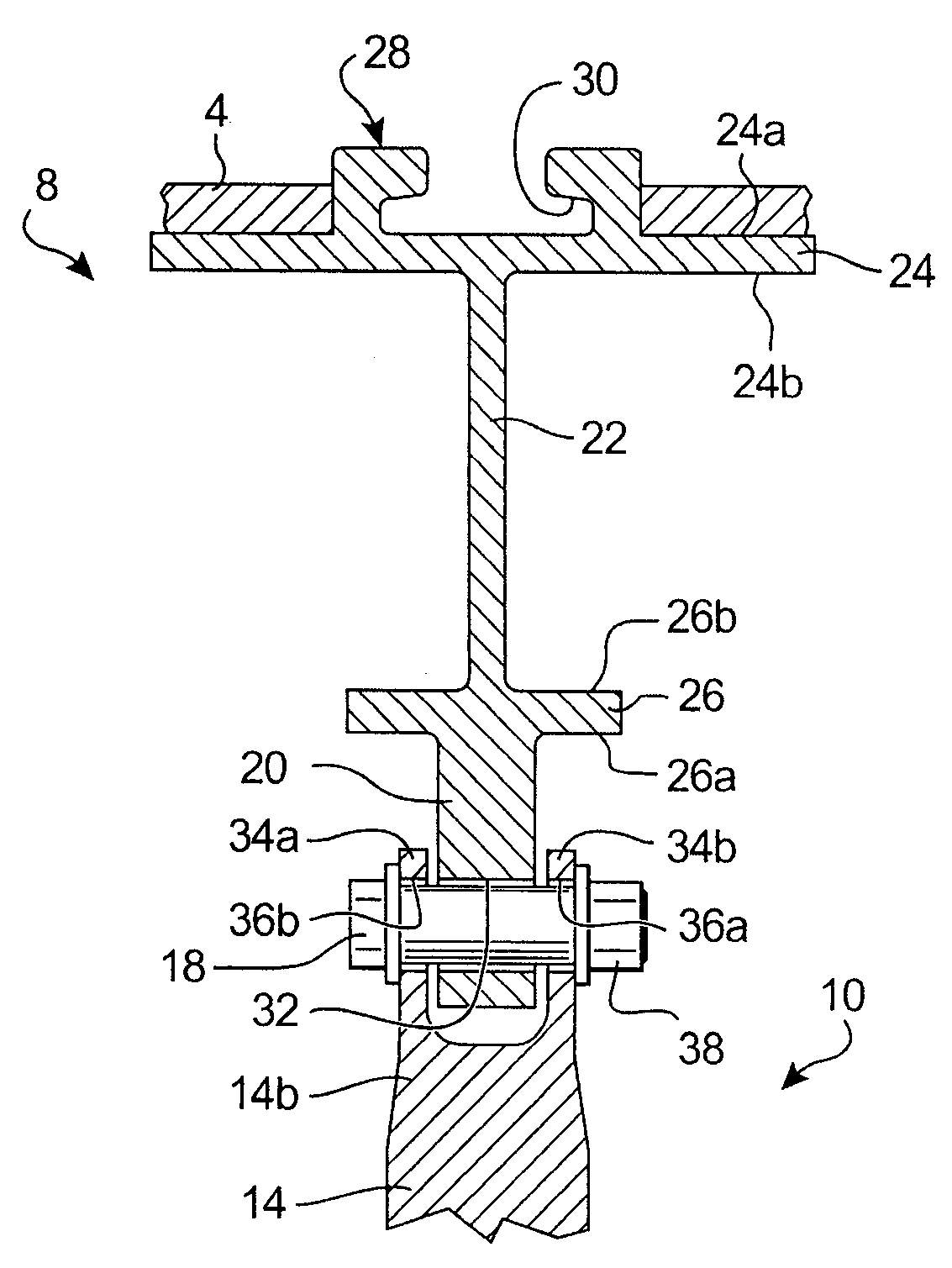
[0037]The seat rail 8 according to the preferred embodiment described is installed rigidly on the aircraft structure 6 located below the floor 4, through several attachment assemblies 10 at a spacing along rail 8. For example, two attachment assemblies 10 directly consecutive to each other and associated with the rail 8 may be...


PUM


Abstract

This invention relates to a seat rail (8) for an aircraft cabin, the rail comprising a web (22) located between a top flange (24) and a bottom flange (26) with an outer surface (26a) and an inner surface (26b) fixed to the web. According to the invention, the rail is also equipped with several connection devices (20) designed for its attachment onto an aircraft structure, and being made in a single piece with the web and the top and bottom flanges, each connection device (20) having at least one through orifice (32) and projecting from the outer surface (26a).

Description

TECHNICAL DOMAIN[0001]This invention relates to a seat rail installed on an aircraft cabin floor in general, and a method of manufacturing such a rail.STATE OF PRIOR ART[0002]This type of rail is well known in prior art. Conventionally it comprises a web located between a top flange and a bottom flange, the top flange being fixed to means of fastening seats.[0003]In a known manner, seat rails are assembled fixed to the aircraft structure below the floor, so as to provide a mechanical support on these same rails. In this respect, note that support is obtained using several attachment assemblies arranged at a spacing from each other along the rail, these assemblies usually comprising a rod connecting the aircraft structure to the web of the rail.[0004]With reference toFIG. 1, a solution is known in prior art consisting of providing a seat rail 100 in which the web 102 is provided with several orifices 104 (only one is shown on the figure), these orifices being treated like rail anchor...

Claims


Application Information

Patent Timeline
Patent Type & Authority Patents(United States)
IPC IPC(8): B64C1/20B64C1/22B64D11/06B64D47/00B64C1/18
CPCB64C1/18B64D11/0696B64C1/20
Inventor RICAUD, ALEXANDRE
Owner AIRBUS OPERATIONS (SAS)
Why Eureka
Try Eureka