Quick-closing valve for the interruption of a fluid flow

a technology of fluid flow and valve, which is applied in the direction of valve details, valve arrangement, operating means/releasing devices, etc., can solve the problems of high cost, short closing time, and additional time, and achieves the effect of shortening the actuation time, facilitating the actuation of the locking element, and reducing the time for the positional change of the locking elemen

Inactive Publication Date: 2007-01-16
ROLLS ROYCE DEUT LTD & CO KG
View PDF25 Cites 9 Cited by
  • Summary
  • Abstract
  • Description
  • Claims
  • Application Information

AI Technical Summary

Benefits of technology

[0008]The present invention, in its essence, provides for the following: in the case of an electrically signaled event demanding rapid interruption of the further fluid supply, the respective closing valve is not shut directly by an electromagnetic force, but solely by mechanical forces which are permanently present at the locked closing element and become effective when the closing element is electromagnetically unlocked. Since only small forces are required to unlock the closing element by means of a small and lightweight solenoid and the actual closing process is effected solely by the permanently present mechanical forces, the closure time—calculated from the moment of triggering the solenoid—is extremely short. Owing to this extremely short closure time, additional—and costly—design measures otherwise dictated for reasons of safety by long closure times can be dispensed with.
[0010]Also, in order to minimize the time for the positional change of the locking element, a lever arrangement is provided between the front face of the valve stem and the locking element to provide for the forces acting upon the locking element and coming from the valve stem. Reduction of the force acting upon the locking element facilitates the actuation of the locking element and shortens the actuating time. Accordingly, the time from the presence of the signal at the locking element to the interruption of the fluid flow is, all in all, in the range of only a few milliseconds. A preferred application field of the present invention is aircraft gas turbines. Here, a signal is generated upon the detection of a shaft failure on the basis of which the inventive quick-closing valve interrupts the further fuel supply in less than 5 milliseconds. This provides for a high safety for persons and material and enables a reduction in the costs for a safe design of the engine.
[0011]In an advantageous further development of the present invention, which is also aimed at a reduction of the shut-off time, the closing element is guided and subject to an additional spring force also on the fluid inlet side.
[0013]The forces acting upon the closing element on the fluid outlet side can be further reduced in that the valve seat is contoured such that a flow duct between the valve seat and the valve disk is created by which a high flow velocity and, thus, a reduction of the static pressure on the fluid outlet side of the closing element are obtained. This provides for a further reduction of the closing time.
[0015]The lever arrangement between valve stem and locking pin, which is intended to facilitate the actuation of the locking pin and reduce the actuating time, is designed such that the locking pin engages the end of the long lever arm of a pivotally angle lever mating with the front face of the valve stem. In a development of this lever arrangement, this angle lever can also be released by means of an interconnected rotary lever which is actuated by the locking pin in its direction of movement.

Problems solved by technology

Since only small forces are required to unlock the closing element by means of a small and lightweight solenoid and the actual closing process is effected solely by the permanently present mechanical forces, the closure time—calculated from the moment of triggering the solenoid—is extremely short.
Owing to this extremely short closure time, additional—and costly—design measures otherwise dictated for reasons of safety by long closure times can be dispensed with.

Method used


Image

  • Quick-closing valve for the interruption of a fluid flow
  • Quick-closing valve for the interruption of a fluid flow
  • Quick-closing valve for the interruption of a fluid flow

Examples


Embodiment Construction

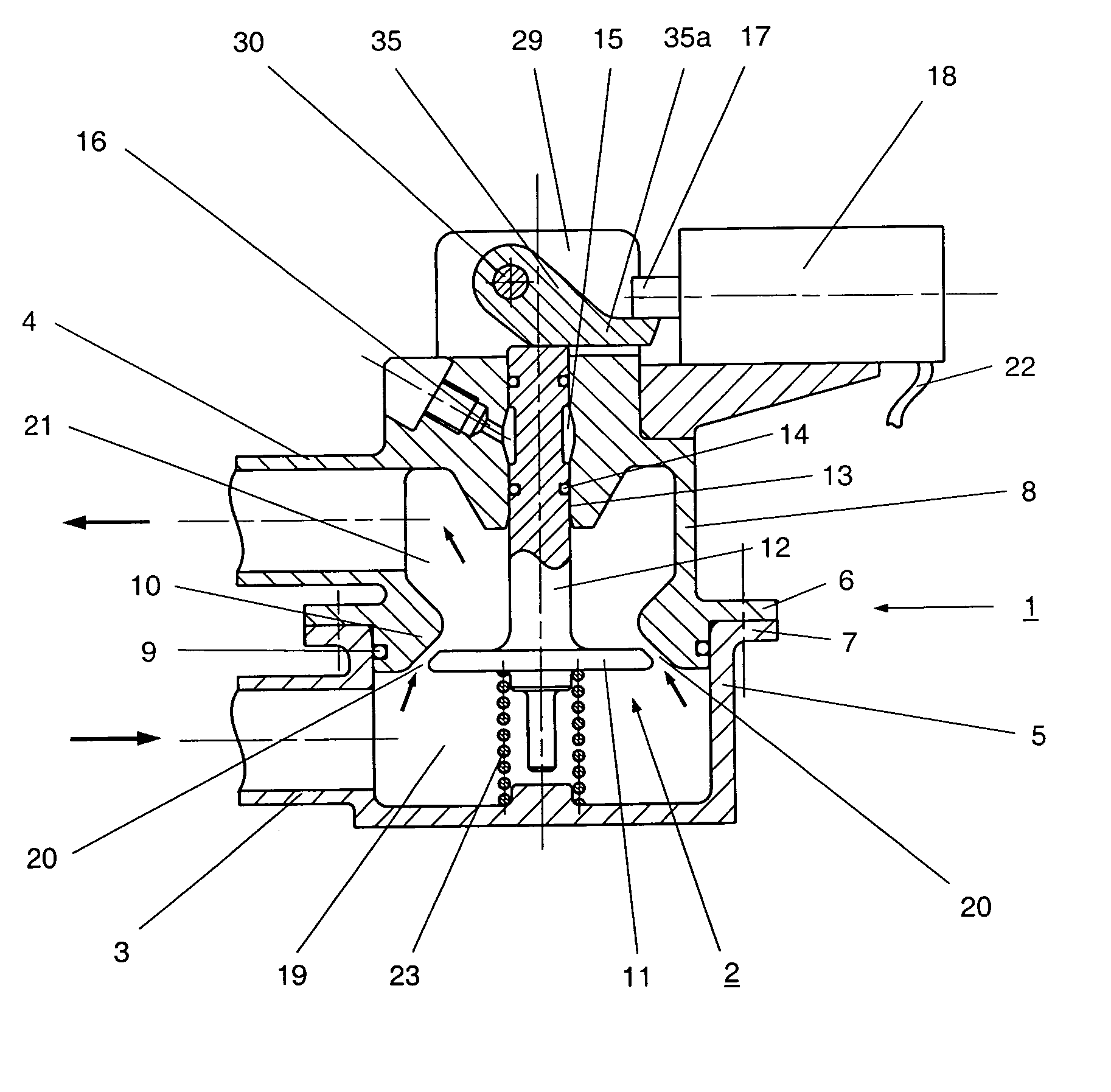
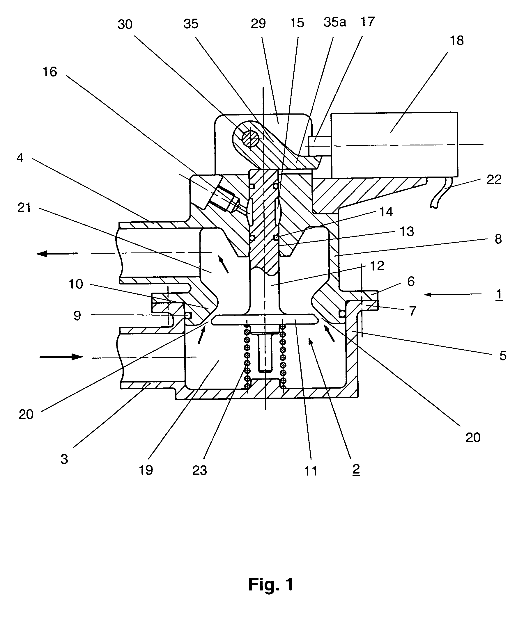
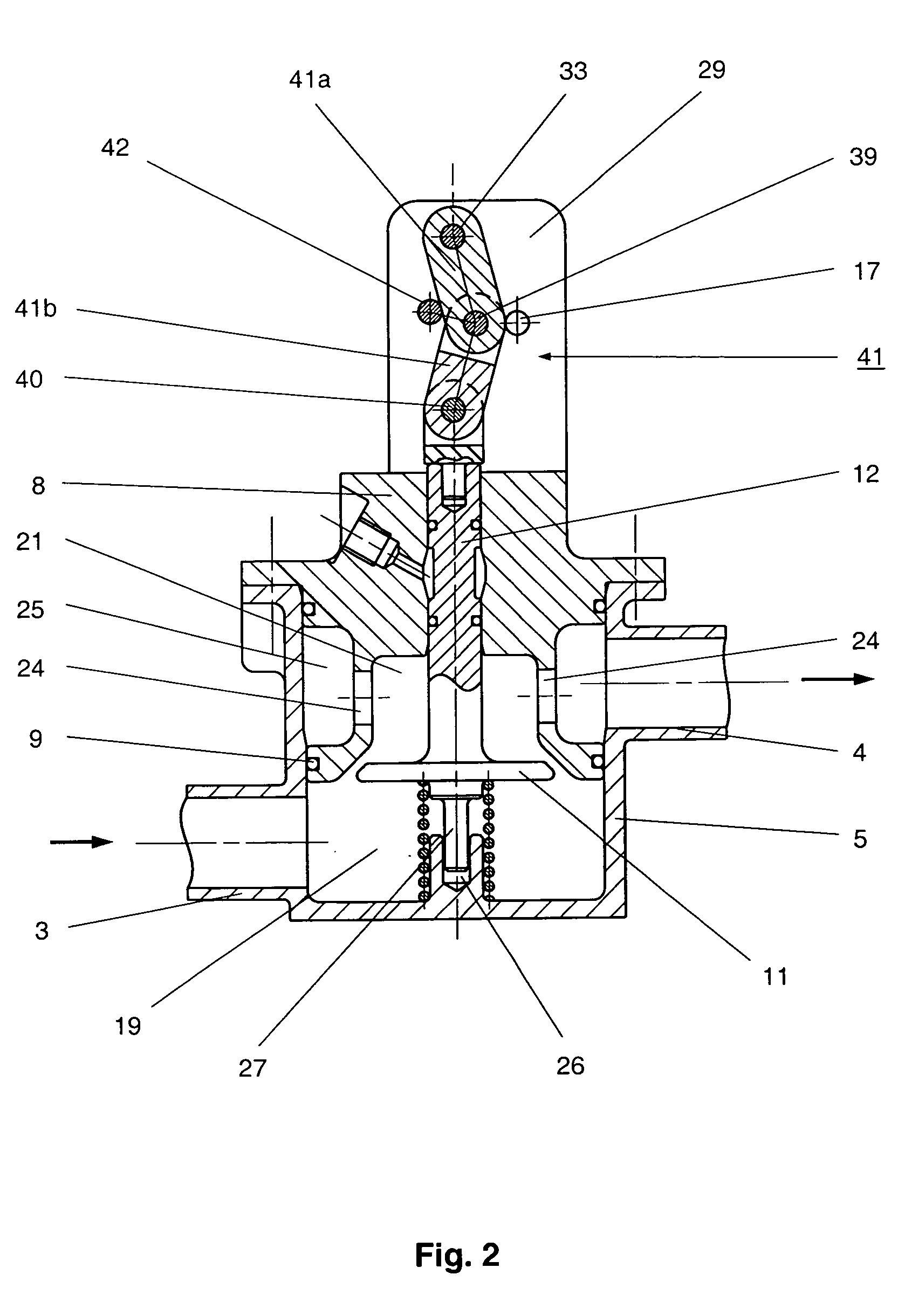
[0021]As shown in FIGS. 1 to 3, the quick-closing valve comprises a valve housing 1, a closing element 2 moveably guided in the valve housing 1, and a trigger mechanism to release the closing movement of the closing element 2 to interrupt the further supply of fuel passing through the valve housing 1 to the combustion chamber of an aircraft gas turbine if a shaft failure is detected and indicated by an electrical signal. The two-part valve housing 1 is incorporated in a fuel line (not shown) via a fluid inlet port 3 and a fluid outlet port 4. It includes a housing base 5 and a housing top 8 attached to the base by means of flanges 6, 7 connected by bolts. Housing seals 9 are provided which seal the housing top to the housing base. The portion of the housing top 8 which engages the housing base 5 and forms a valve seat 10 for a valve disk 11 of the closing element 2 whose valve stem 12 is guided in a valve stem guide 13 provided in the housing top 8 and is sealed in the valve stem gu...


PUM


Abstract

A valve housing 1 with valve seat 10 incorporated in a fluid line features a closing element 2 with a valve disk 11 and a valve stem 12 extending through and sealed in the housing wall which, on the outer side, is locked by means of a locking pin 17 actuated by a solenoid. Owing to the geometry of the valve disk and the annular gap 20 as well as the action of a spring element 23, the inlet-side pressure acting upon the closing element 2 exceeds the outlet-side pressure, as a result of which the fluid flow via the annular gap is interrupted in only a few milliseconds merely by the permanently present, higher mechanical pressure if the valve stem is released merely by the movement of the locking pin effected by a small and lightweight solenoid 18, actuated on the basis of a signal indicating an event.

Description

[0001]This application claims priority to German Patent Application DE10357423.9 filed Dec. 4, 2003, the entirety of which is incorporated by reference herein.BACKGROUND OF THE INVENTION[0002]This invention relates to a quick-closing valve for the interruption of a fluid flow, in particular, for the interruption of the fuel supply to an aircraft gas turbine in the event of a shaft failure, which comprises a valve housing with a valve seat and a closing element and is incorporated in a fluid line via a fluid inlet and a fluid outlet port.[0003]In many applications, it is necessary to interrupt a media flow as quickly as possible. In the case of jet engines, for example, a shaft failure, in particular the failure of the low-pressure turbine shaft, constitutes a considerable danger to persons and property. In the event of a shaft failure, the energy-producing side of the shaft, which is now detached from the energy-consuming side, will speed up in an uncontrolled manner. Consequently, ...

Claims


Application Information

Patent Timeline
Patent Type & Authority Patents(United States)
IPC IPC(8): F16K31/44F16K31/00F16K31/06F16K31/56
CPCF16K31/003F16K31/56F16K31/06
Inventor OPPER, HANS OTTO
Owner ROLLS ROYCE DEUT LTD & CO KG
Why Eureka
Try Eureka