Bumper for pedestrian impact having thermoformed energy absorber

a technology of energy absorber and bumper, which is applied in the direction of bumper, roof, pedestrian/occupant safety arrangement, etc., can solve the problems that the skilled artisans in bumper design have not fully realized the unexpected, and the most injection-molded energy absorber, etc., to reduce pedestrian injury during impact, softer impact, and thicker cross section

Inactive Publication Date: 2007-01-16
NETSHAPE INT LLC
View PDF73 Cites 58 Cited by
  • Summary
  • Abstract
  • Description
  • Claims
  • Application Information

AI Technical Summary

Benefits of technology

[0008]In yet another aspect of the present invention, a bumper system for vehicles includes a beam and a thermoformed energy absorber positioned on a face of the beam. The thermoformed energy absorber has a base flange, and has a plurality of spaced-apart crush boxes thermoformed from the base flange. The crush boxes are longitudinally elongated to at least three times their width. Some of the crush boxes are near a center of the beam and extend forward of the beam a first distance in height, and some of the crush boxes are near ends of the beam and extend forward of the beam a second distance in height, the first distance being at least double the second distance. The crush boxes each include a front section spaced from the base flange and including top, bottom, and fore-aft-extending side walls that extend from the front section to the base flange. The side walls have a non-constant thickness and are tapered in shape due to being stretched when thermoformed, the crush boxes near the center of the beam that are the first distance in height having a front portion of the fore-aft-extending walls that is less than about half of a thickness of the base flange. The crush boxes near the ends of the beam that are a second distance in height have a thicker cross section than the crush boxes near the center, such that the center area has a softer impact intended to reduce pedestrian injury during impact.

Problems solved by technology

Further, most injection-molded energy absorbers made of solid polymer are relatively complex parts with undercut surfaces, varied wall thicknesses, and different wall spacings to provide optimal energy absorption in different regions of the energy absorbers.
Skilled artisans in bumper design have apparently not fully realized the unexpected added benefits that thermoformed parts can offer when combined with other energy absorbing systems and components.

Method used


Image

  • Bumper for pedestrian impact having thermoformed energy absorber
  • Bumper for pedestrian impact having thermoformed energy absorber
  • Bumper for pedestrian impact having thermoformed energy absorber

Examples


Embodiment Construction

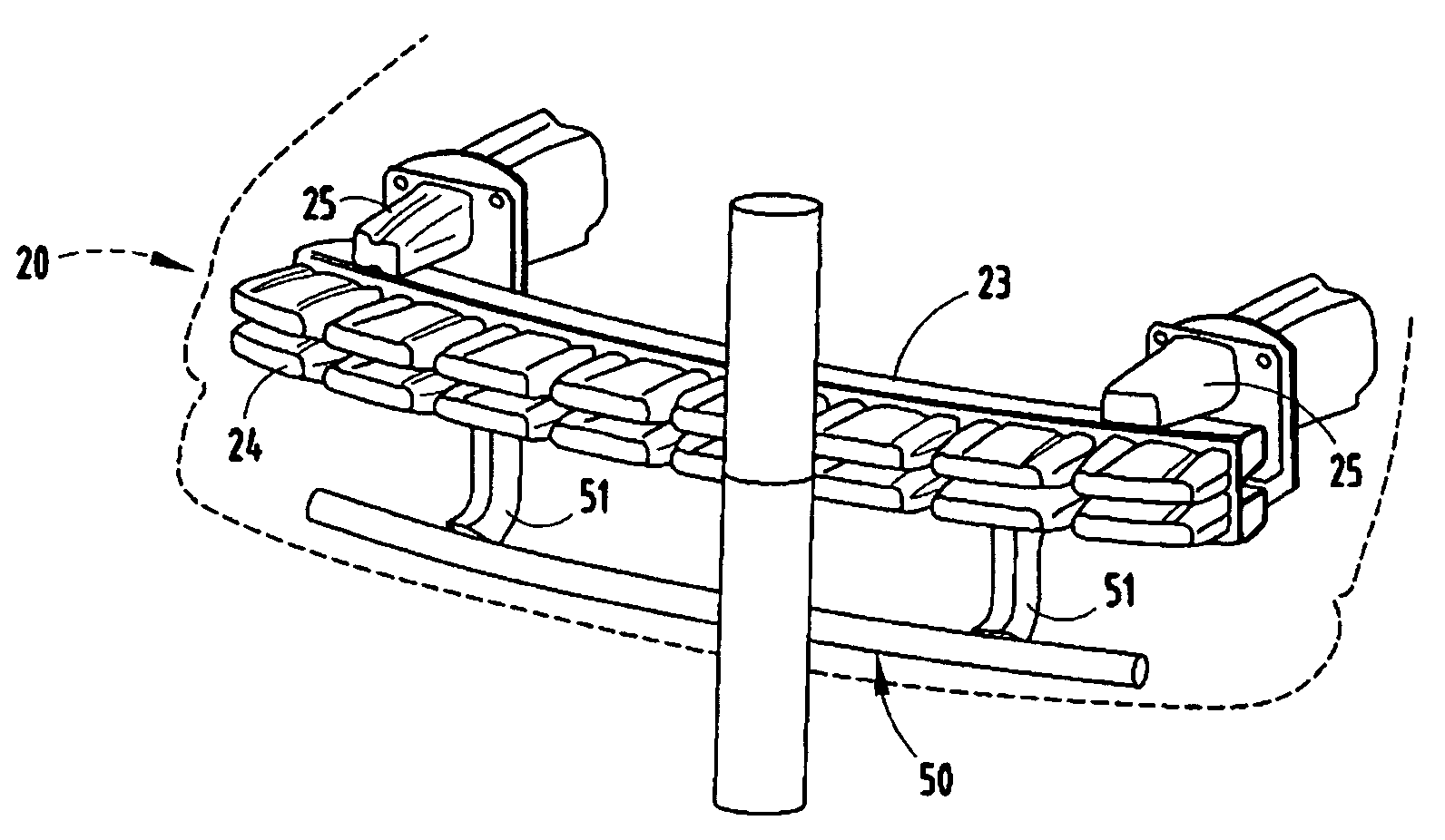
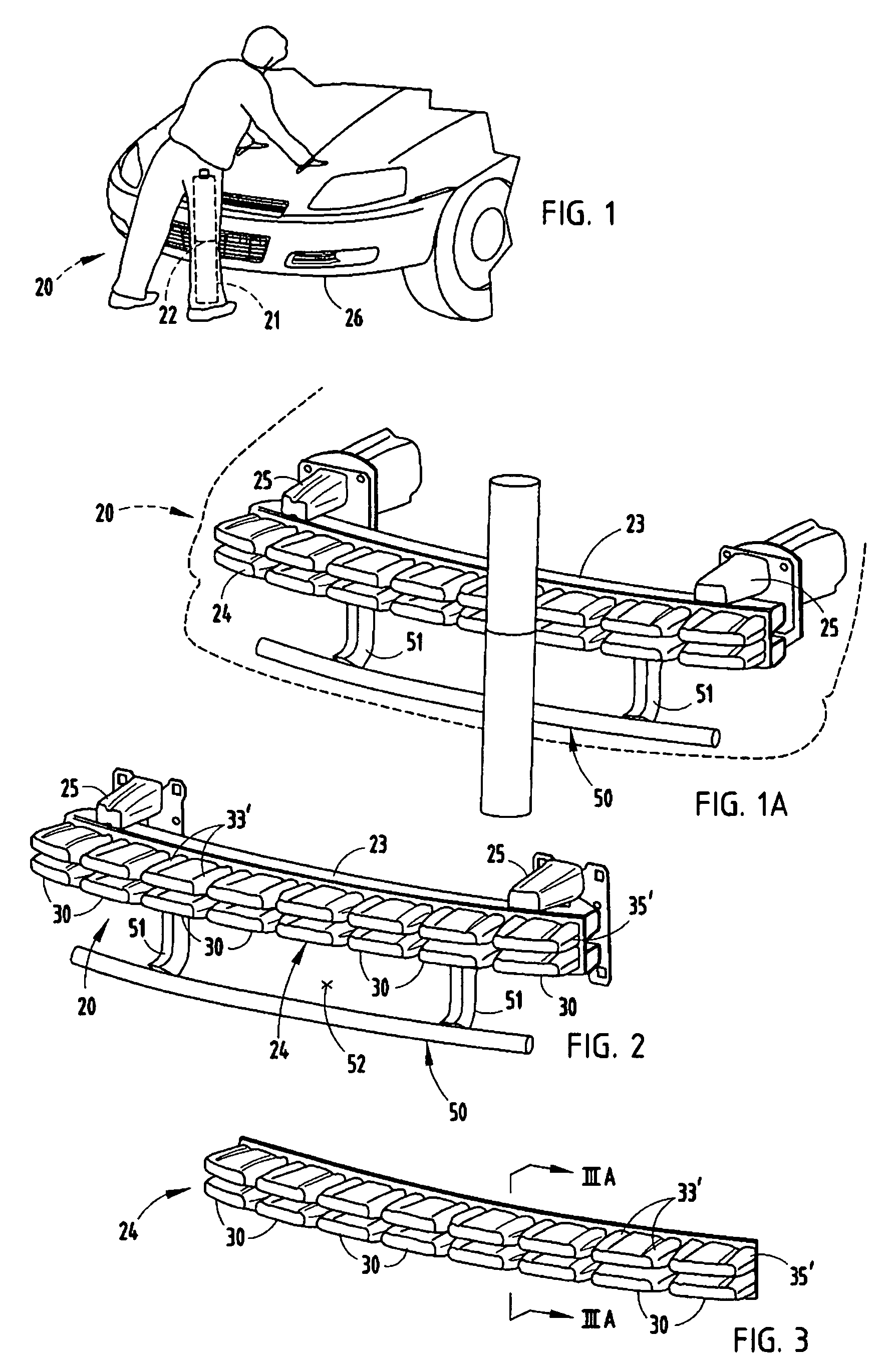
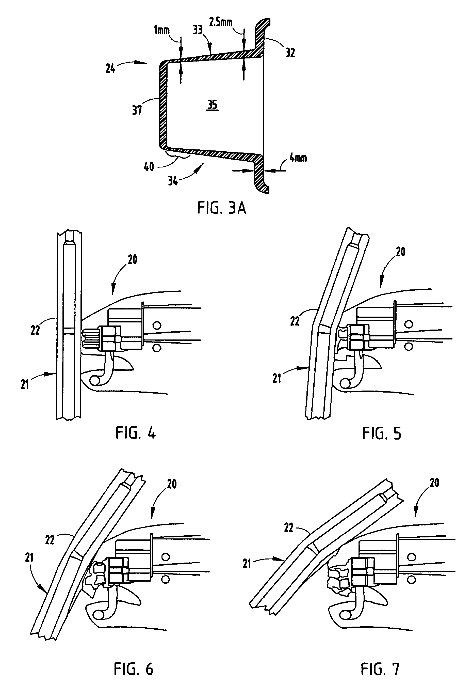
[0022]A vehicle bumper system 20 (FIG. 1) is configured to provide an improvement where pedestrian injury due to impact is reduced, such as injury to the pedestrian's leg 21 especially at his or her knee 22. The bumper system 20 includes a beam 23 and a thermoformed energy absorber 24 positioned on a face of the beam 23. The beam 23 is mounted to a vehicle frame by mounts 25, and the beam 23 and energy absorber 24 are configured to support fascia 26 that aesthetically covers the vehicle front end.

[0023]The thermoformed energy absorber 24 is made from a sheet of material, such as a thermoformable polyolefin. The absorber 24 has a plurality of deep-drawn longitudinally-elongated crush boxes 30 thermoformed from a base flange 32. The crush boxes 30 are up to about three inches deep, and as a result have side walls that are stretched when thermoformed. As a result, the center area has a relatively soft impact intended to reduce pedestrian injury in an accident, as shown in FIGS. 4–5. Du...


PUM


Abstract

A vehicle bumper system includes a beam and a thermoformed energy absorber positioned on a face of the beam. The thermoformed energy absorber has a plurality of elongated crush boxes thermoformed from a base flange. Crush boxes near a center of the beam are up to about three inches deep, and as a result have side walls that are stretched when thermoformed, while crush boxes near ends of the beam are much shorter and hence not as thin. As a result, the center area has a softer impact intended to reduce pedestrian injury during impact.

Description

CROSS-REFERENCE TO RELATED APPLICATIONS[0001]This application claims benefit of provisional application Ser. No. 60 / 635,655, filed Dec. 13, 2004, entitled BUMPER FOR PEDESTRIAN IMPACT HAVING THERMOFORMED ENERGY ABSORBER, the entire contents of which are incorporated herein in their entirety.BACKGROUND[0002]The present invention relates to vehicle bumper systems configured to reducing injury to pedestrians upon impact.[0003]Modern bumper systems are designed to absorb a maximum of impact energy over a given stroke. At the same time, they are designed to minimize load spikes, and to distribute energy in a manner promoting uniform and predictable collapse upon undergoing a vehicle crash. Every millimeter of space is important to energy absorption, even spaces of 10 mm or less. Further, the individual components of an energy-absorbing system must combine well with other energy-absorbing components, e.g., metal tubular beams and non-tubular channels, injection-molded “honeycomb” energy a...

Claims


Application Information

Patent Timeline
Patent Type & Authority Patents(United States)
IPC IPC(8): B60R19/18B60R21/34
CPCB60R19/12B60R19/18B60R2019/1846B60R21/34
Inventor EVANS, DARIN
Owner NETSHAPE INT LLC
Why Eureka
Try Eureka