Push switch

a push switch and switch technology, applied in the field of push switches, can solve the problem and achieve the effect of weakened noise caused by bouncing impa

Inactive Publication Date: 2007-01-16
ALPS ALPINE CO LTD
View PDF7 Cites 21 Cited by
  • Summary
  • Abstract
  • Description
  • Claims
  • Application Information

AI Technical Summary

Benefits of technology

[0018]By the above construction, since the operating body slides while abutting the first and second tapered surfaces, an impact noise caused by bouncing is weakened. In addition, since the operating body regulating portion abuts on the casing regulating portion to regulate the location of the operating body, the operating body can be easily positioned.
[0020]By the above construction, since the tapered surfaces are provided to be separated from each other, the sliding becomes more stable.
[0022]By the above construction, the structure for preventing the noise from being generated during the return of the operating body and the structure for positioning the operating body can be simplified.
[0027]According to the present invention, since the sliding occurs in contact between the first and second tapered surfaces, the noise caused by the bouncing is weakened. Since the operating body regulating portion abuts on the casing regulating portion to regulate the position of the operating body, the operating body can be surely positioned.

Problems solved by technology

By the above construction, since the operating body slides while abutting the first and second tapered surfaces, an impact noise caused by bouncing is weakened.

Method used


Image

  • Push switch
  • Push switch
  • Push switch

Examples


first embodiment

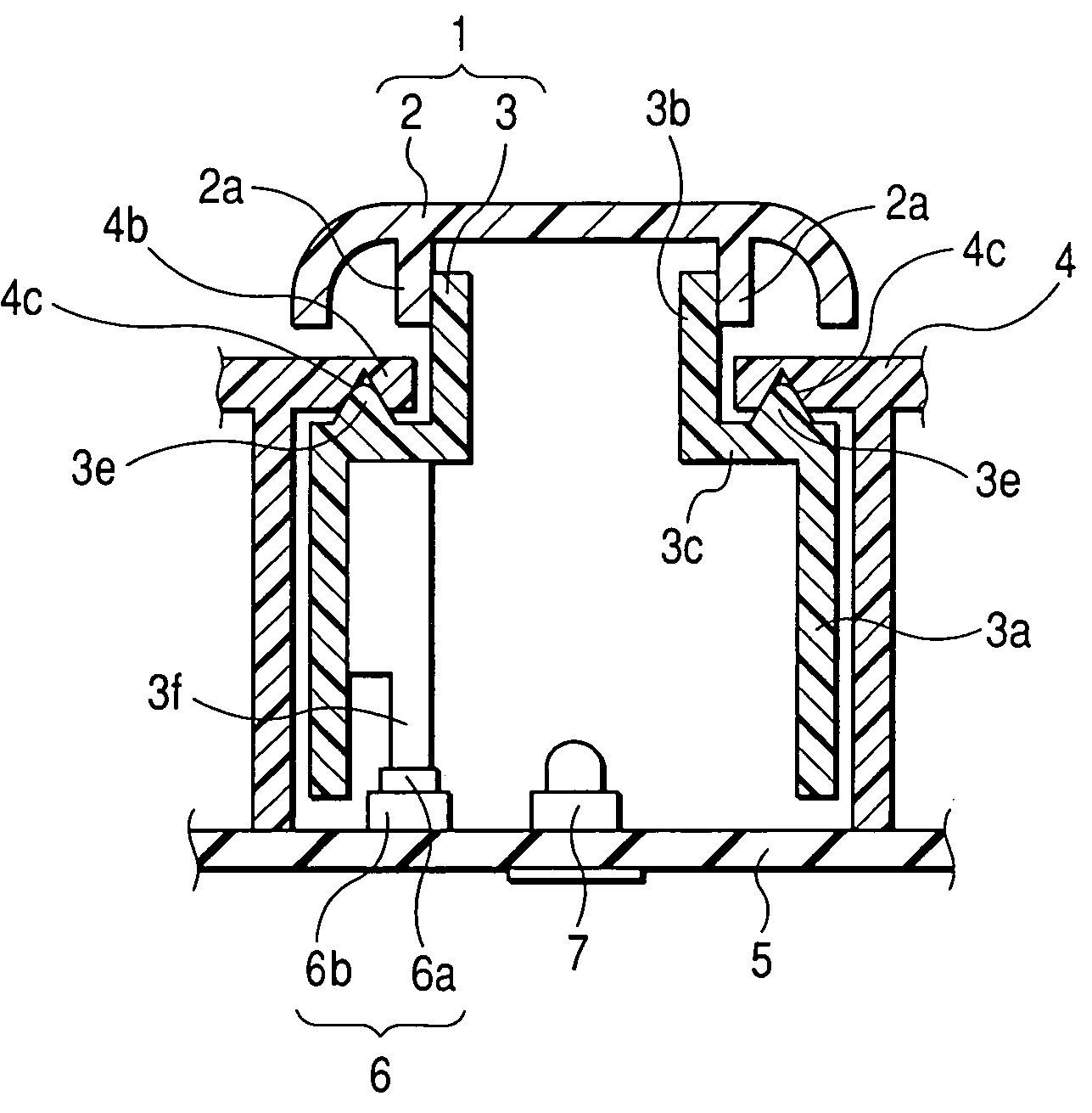
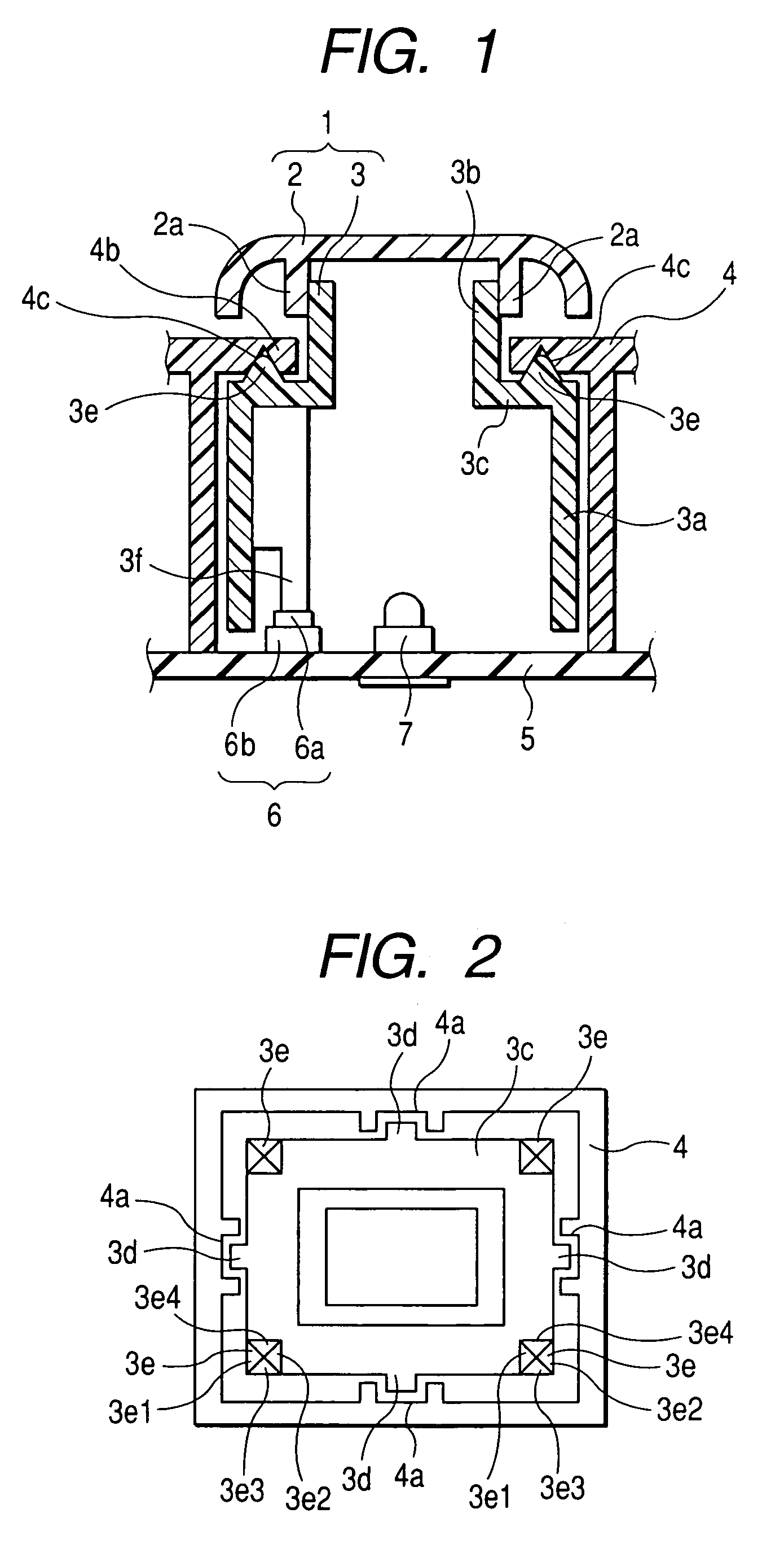
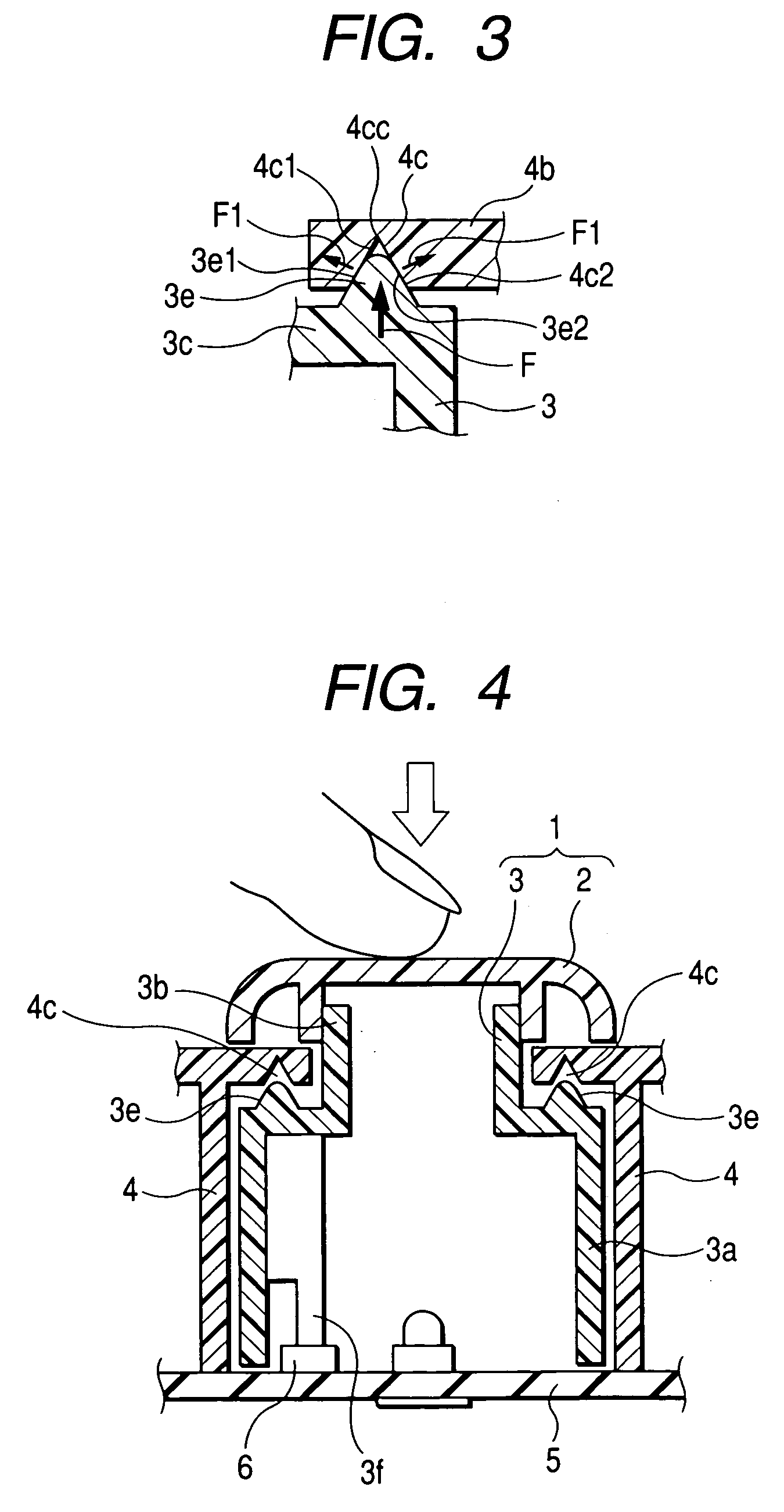
[0039]FIG. 1 is a sectional view showing the state where a push switch related to a first embodiment of the present invention is not pressed. FIG. 2 is a transverse sectional view showing the push switch shown in FIG. 1. FIG. 3 is an enlarged sectional view showing main parts of the push switch in FIG. 1. FIG. 4 is an explanatory view showing the operation state of the push switch shown in FIG. 1. FIG. 5 is an explanatory view showing the operation state of the push switch shown in FIG. 1. FIG. 6 is an explanatory view showing the operation which prevents generation of an impact noise. FIG. 7 is an explanatory view showing the operation of the push switch according to the embodiment. In addition, the inclination and clearance of an operating body are indicated larger than an actual size in the drawings.

[0040]In the push switch of the present embodiment, as shown in FIGS. 1 to 7, reference numeral 1 denotes the operating body as a whole, the operating body 1 is composed of a knob 2 a...

second embodiment

[0068]FIG. 8 is a sectional view showing main parts of a push switch related to a second embodiment of the present invention.

[0069]In this embodiment, a tab 8 protrudes from the middle of the slider 3. With respect to the tab 8, a tapered surface 9a is provided one side of the slider, and another tapered surface 9b parallel to the tapered surface 9a is provided on the other side of the slider. These tapered surfaces 9a and 9b are inclined from the operating direction of the slider 3. Tapered surfaces 10a and 10b corresponding to the tapered surfaces 9a and 9b are provided in the casing 4. Also, flat surfaces 11 and 12 are provided.

[0070]By these tapered surfaces 9a, 9b, 10a and 10b, as the sliding occurs during the return of the slider 3 as described above, the moving speed of the slider 3 is decreased. As a result, generation of an impact noise is prevented. In the present embodiment, the tapered surfaces 9a and 10a are equivalent to the first tapered surfaces, the tapered surfaces...


PUM


Abstract

A slider is provided with projections. Each projection is formed with tapered surfaces. A casing is provided with concave portions having the same shape as the projections. During the return of an operating body, the slider ascends while being inclined, and the slider stands upright as the tapered surface of the projection and the tapered surface of the concave portion of the casing slide on each other. Then, each projection is fitted into the corresponding concave portion, thereby positioning the slider.

Description

[0001]This application claims the benefit of priority to Japanese Patent Application No. 2004-172695 filed on Jun. 10, 2004, herein incorporated by reference.BACKGROUND OF THE INVENTION[0002]1. Field of the Invention[0003]The present invention relates to a push switch which prevents an impact noise from being generated during the return of a slider after the slider is pressed.[0004]2. Description of the Related Art[0005]A push switch is publicly known in Japanese Unexamined Utility Model Registration Application Publication No. 5-55420 and shown in FIGS. 9 and 10. In the push switch, an operating member is pressed to bring a movable contact into contact with and separated from a fixed contact, and the movable contact and the fixed contact are accommodated in a casing. If the pressing is released by a return member, these contacts return to their initial positions. Section lines in FIGS. 9 and 10 pass through a front leg and a rear leg which will be described later.[0006]In the drawi...

Claims


Application Information

Patent Timeline
Patent Type & Authority Patents(United States)
IPC IPC(8): H01H9/00H01H13/14F16K51/00H01H3/12H01H13/02
CPCH01H3/12H01H2221/058H01H2221/026H01H13/023
Inventor KAWANO, KENJI
Owner ALPS ALPINE CO LTD
Why Eureka
Try Eureka