
Open-loop voltage driving of a DC motor

a dc motor and open-loop voltage technology, applied in the field of electric motors, can solve the problems of increasing the cost of a complete integrated circuit with the number of pins, complicated control, and relatively expensive externally connected discrete components

Active Publication Date: 2007-01-16
STMICROELECTRONICS SRL
View PDF26 Cites 55 Cited by
  • Summary
  • Abstract
  • Description
  • Claims
  • Application Information

AI Technical Summary

Benefits of technology

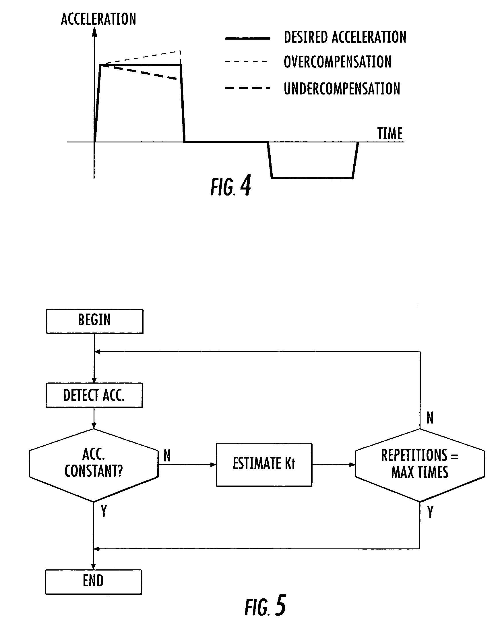
The present invention provides a method for controlling the voltage of a DC motor to address issues with existing methods. The method uses an open-loop control system that adjusts the driving voltage of the motor based on its speed. This compensates for the back electromotive force, which is the voltage generated by the motor when it is running. The method ensures that any changes in acceleration are minimized, resulting in a more stable motor control. The method can be easily implemented in existing control circuits and can also be used to determine the speed constant of the motor.

Problems solved by technology

This delay or phase lag complicates the control and may lead to relevant errors in precisely positioning devices moved by the motor.
Drawbacks connected to this type of driving include that the sensing resistor must be highly precise to minimize driving errors of the motor, and it is a relatively expensive externally connected discrete component.
With even larger scale of integration the cost of completely packaged integrated circuits increases with the number of pins.
An undesired effect in driving DC motors includes that when the rotation speed of the rotor increases, the back electromotive force induced in the primary winding, that contrasts the rotation of the rotor, also increases.
Unfortunately, the speed constant Kt varies during the operation of the motor, primarily because of the heating up of the windings, and it may differ significantly from its design value, thus the method disclosed in the cited patent application does not ensure a sufficiently accurate compensation of the back electromotive force for applications in which a precise driving of the motor is required.

Method used


Image

  • Open-loop voltage driving of a DC motor
  • Open-loop voltage driving of a DC motor
  • Open-loop voltage driving of a DC motor

Examples


Embodiment Construction

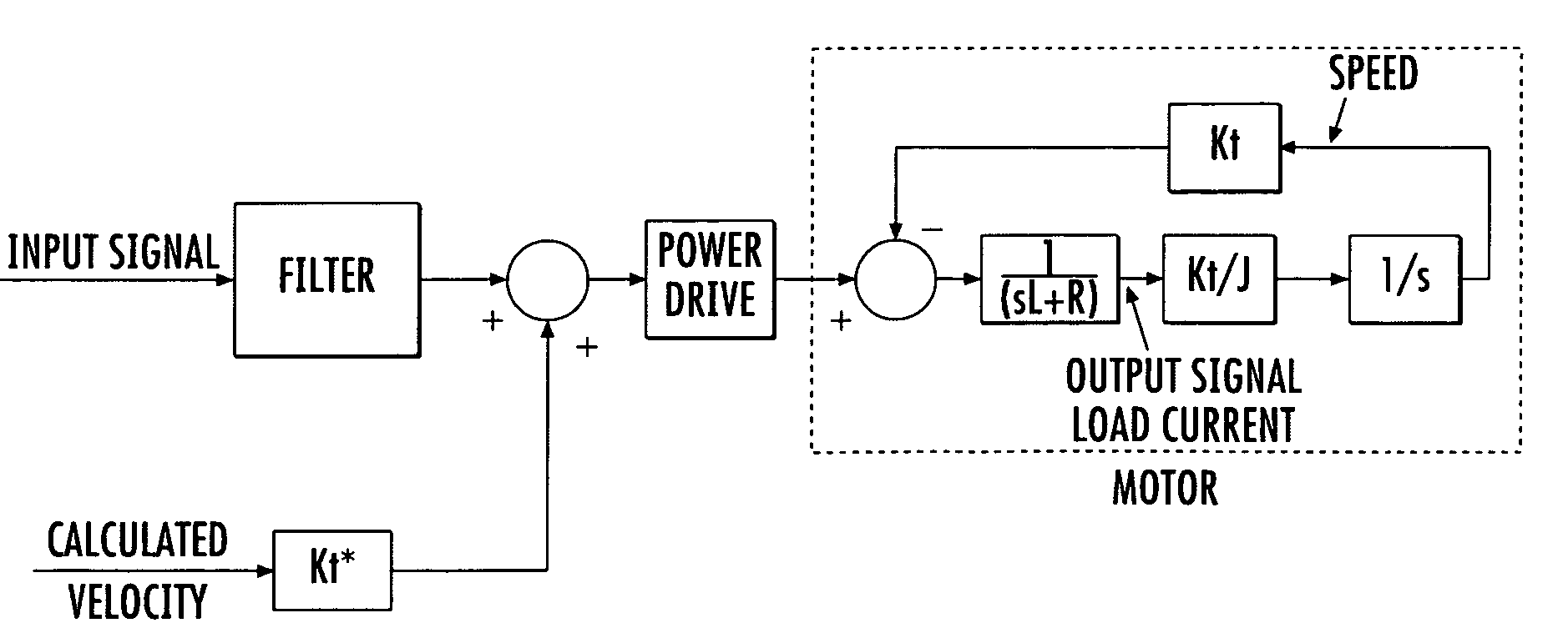
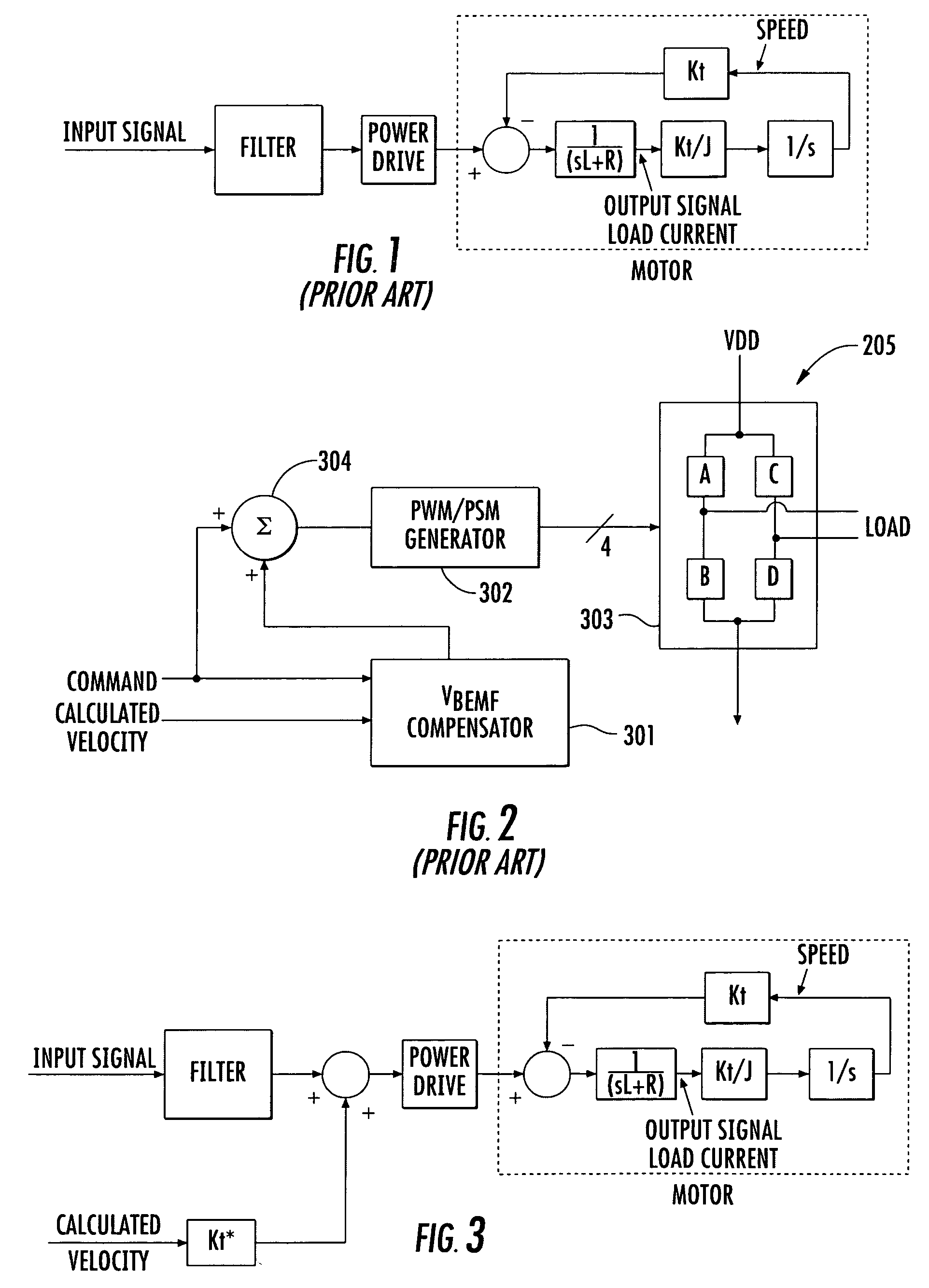
[0020]The open-loop driving method of this invention substantially includes increasing the driving voltage V of the motor of a quantity proportional to the speed of the motor ω according to a proportionality factor Kt* the value of which is continuously determined to precisely compensate the back electromotive force VBEMF.

[0021]This may be done very simply with the driving circuit of FIG. 3, similar to that of the prior art depicted in FIG. 2, with the addition of the output driving voltage of the compensation filter FILTER being incremented by the quantity Kt*·ω, in a compensation block that may have some gain. Therefore, the equation that describes the effective excitation voltage of the armature circuit VMOTOR is no longer equation (2) of the prior art, but the following:

VMOTOR(t)=V(t)+Kt*·ω(t)−Kt·ω(t)  (3)

[0022]The value of the proportionality factor Kt* is constantly defined to precisely compensate the back electromotive force. Clearly, if Kt*>Kt or Kt*<Kt, the back electromoti...


PUM

PropertyMeasurementUnit
speed constantaaaaaaaaaa
constant accelerationaaaaaaaaaa
driving voltageaaaaaaaaaa

Abstract

The driving voltage of the motor is incremented a quantity proportional to the speed of the motor according to a proportionality factor that is adjusted to compensate the back electromotive force. A method includes open-loop voltage control of a DC motor having a certain design speed constant, through a driving signal that is determined for imparting a certain acceleration to the motor and by generating a driving voltage of an output power stage to which the winding of the motor is connected as a function of the driving signal.

Description

FIELD OF THE INVENTION[0001]The present invention relates to electric motors, and, more particularly, to a method and circuit for open-loop voltage-mode control of a DC motor, such as for example a voice coil motor (VCM).BACKGROUND OF THE INVENTION[0002]In many applications it is necessary to drive DC motors with great precision. Electric motors are inductive loads and thus there is a certain delay between a variation of the current circulating in the motor winding(s) and the corresponding voltage variation at the terminals of the motor. The delay is a function of the electrical time constant of the motor. This delay or phase lag complicates the control and may lead to relevant errors in precisely positioning devices moved by the motor.[0003]An important application requiring a precise driving of a motor is that in which a voice coil motor (VCM) is used for shifting read / write heads over the surface of hard disk. There are innumerable applications of voice coil motors, and for sake ...

Claims


Application Information

Patent Timeline
Patent Type & Authority Patents(United States)
IPC IPC(8): G05B11/01G11B15/18
CPCH02P25/028G11B5/5547H02P25/034
Inventor BOSCOLO, MICHELECAPRETTA, PAOLO
Owner STMICROELECTRONICS SRL
Learn More