Automated control mechanism for a snow blower discharge chute

a control mechanism and snow blower technology, applied in snow cleaning, way cleaning, construction, etc., can solve the problems of added parts, automatic swivelling discharge chute, and difficult operation of snow blower at the same tim

Inactive Publication Date: 2007-01-23
BEAUDOIN GILLES JOSEPH
View PDF8 Cites 14 Cited by
  • Summary
  • Abstract
  • Description
  • Claims
  • Application Information

AI Technical Summary

Problems solved by technology

There are many different designs, but few have automated swivelling discharge chutes.
Most snow blowers have a crank that must be manually rotated to swivel the chute in the proper direction, making it difficult to operate the snow blower at t...

Method used


Image

  • Automated control mechanism for a snow blower discharge chute
  • Automated control mechanism for a snow blower discharge chute
  • Automated control mechanism for a snow blower discharge chute

Examples


Embodiment Construction

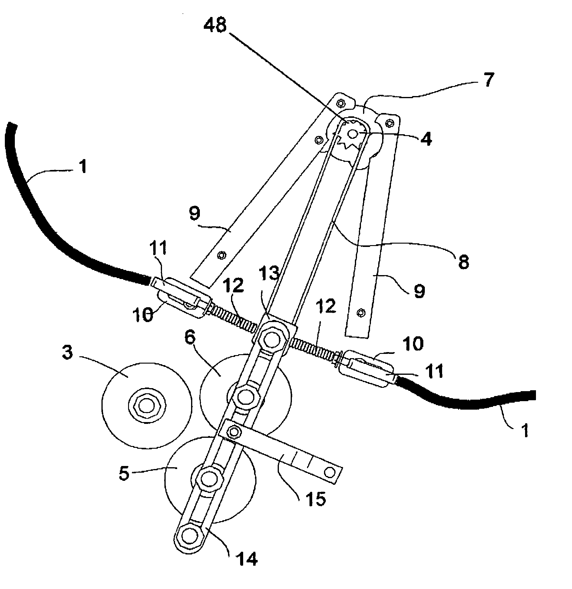
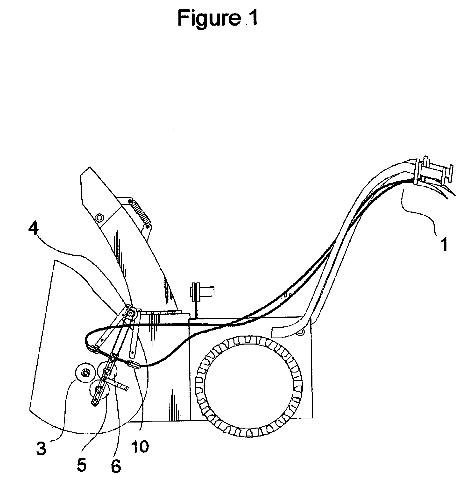
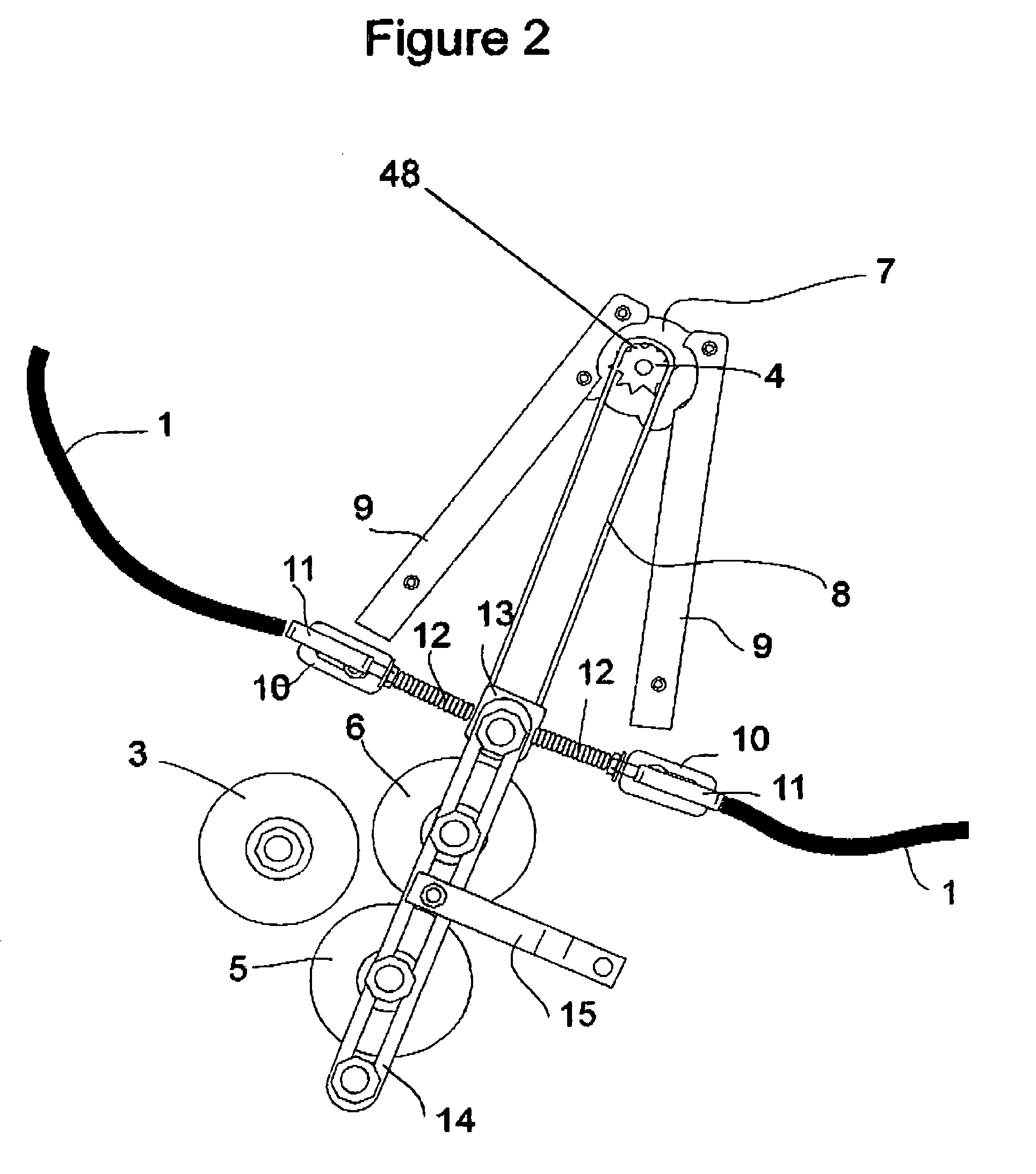
[0010]The automated control mechanism for the swivelling snow discharge chute essentially consists of a rubber disc 3 that drives the chain 8 to rotate the worm gear 21. The rubber disc 3 is bolted to the auger of the snow blower, which is the driving force needed to rotate the snow discharge chute. Discs 5 and 6 are bolted to two swivelling brackets 14 that is beside the disc 3 connected to the auger. The bottom rubber disc 5 contains two bearing 36 press-fit into each side of the disc 5. The rubber disc 5 is mounted to the brackets 14 using a bolt 39 and it is secured in place with a washer 46 and nut 37. The top disc 6 is bolted to a washer 40. Washer 40 is welded onto the shaft 41 and bolted through disc 6 and washer 42 with three bolts 45. The shaft 41 rests inside of two bearings 38, which is press-it into the brackets 14. This provides the easy rotation of the rubber disc 6.

[0011]The swivelling brackets 14 are bolted to the shroud, and held in place with retaining bar 15. The...


PUM


Abstract

The automation mechanism has of three rubber discs, two of which are connected to two swiveling brackets. The brackets are directed by two cables and two cable levers, each one connected to each handlebar. The swivelling brackets consist of two rubber discs that make contact to the center disc at the left side of the shroud. This center disc is connected to the rotating snow auger inside the shroud, which is the driving force for this invention. When one of the rubber discs makes contact with the rotating rubber disc at the center, it rotates a drive chain that is connected to a sprocket near the discharge chute. The sprocket rotates a clutch that rotates a worm gear, and in turn, rotates the discharge chute. Once the discharge chute reaches its maximum rotating limit, the clutch disengages by slipping. The operator can move the chute either right or left by pulling on either the left or right lever on the handlebars, while operating the snow blower at the same time. The auger must be engaged in order for the swivelling discharge chute to work.

Description

BACKGROUND OF THE INVENTION[0001]Snow blowers are a common tool used particularly in colder climates. There are many different designs, but few have automated swivelling discharge chutes. Most snow blowers have a crank that must be manually rotated to swivel the chute in the proper direction, making it difficult to operate the snow blower at the same time. Those that do have automated discharge chutes are driven by a separate electric motor, which also requires a battery and a greater magneto. These added parts adds considerable cost and complexity to the construction of the snow blower. Those that are driven by the engine are mechanically complex, expensive to build and demonstrate considerable wear on rapidly rotating parts. Typical automated snow chutes of these types are shown, for example, in the following patents from the United Kingdom, the United States of American and Canada:[0002]U.S. Pat. No. 5,444,927 Mar. 7, 1994 SOSENKO; EP0372150 Jun. 13, 1990 HANYU; U.S. Pat. No. 6,0...

Claims


Application Information

Patent Timeline
IPC IPC(8): E01H5/09E01H5/04
CPCE01H5/045
Inventor BEAUDOIN, GILLES JOSEPH
Owner BEAUDOIN GILLES JOSEPH
Why Eureka
Try Eureka