Bearing assembly

a technology of bearings and components, applied in the direction of bearings, rigid supports of bearing units, braking systems, etc., can solve the problems of significant waste (in terms of scrap material), machining also consumes a considerable amount of tooling, and the bearing may not function properly

Inactive Publication Date: 2012-09-25
OCONOMOWOC MFG
View PDF4 Cites 5 Cited by
  • Summary
  • Abstract
  • Description
  • Claims
  • Application Information

AI Technical Summary

Problems solved by technology

There is, for example, significant waste (in terms of scrap material) in the machining required to give the exterior of the shaft the contour that defines the inner race.
This machining also consumes a considerable amount of tooling.
Further, if this machining is not done accurately, then the bearing may not function properly.
Still further, because the stamped plate SP is staked to one end of the shaft IS, the shaft cannot be hardened sufficiently without great expense.
As a result, the inner race wears faster than other bearing components.
This shortens the life of the bearing.

Method used


Image

  • Bearing assembly
  • Bearing assembly
  • Bearing assembly

Examples


Embodiment Construction

[0021]The following detailed description is to be read with reference to the drawings, in which like elements in different drawings have like reference numbers. The drawings, which are not necessarily to scale, depict selected embodiments and are not intended to limit the scope of the invention. Skilled artisans will recognize that the given examples have many alternatives that fall within the scope of the invention.

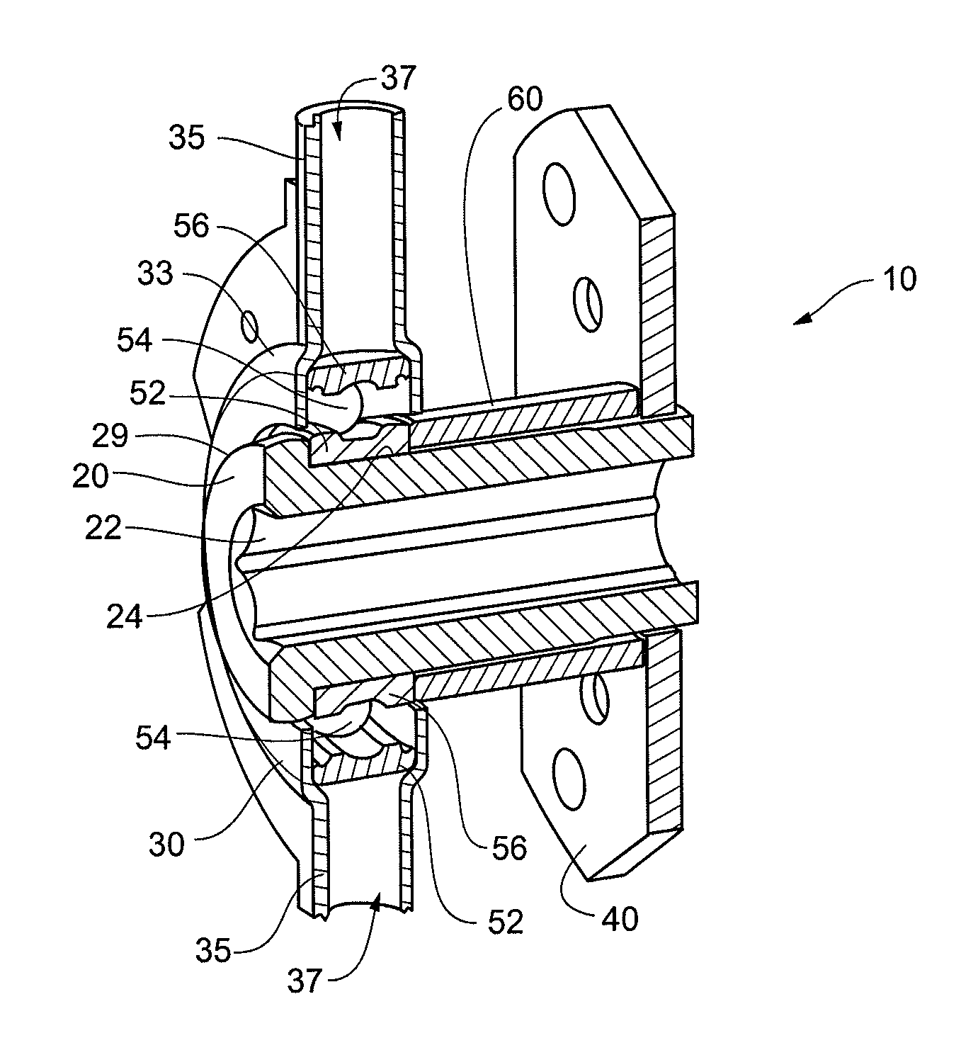
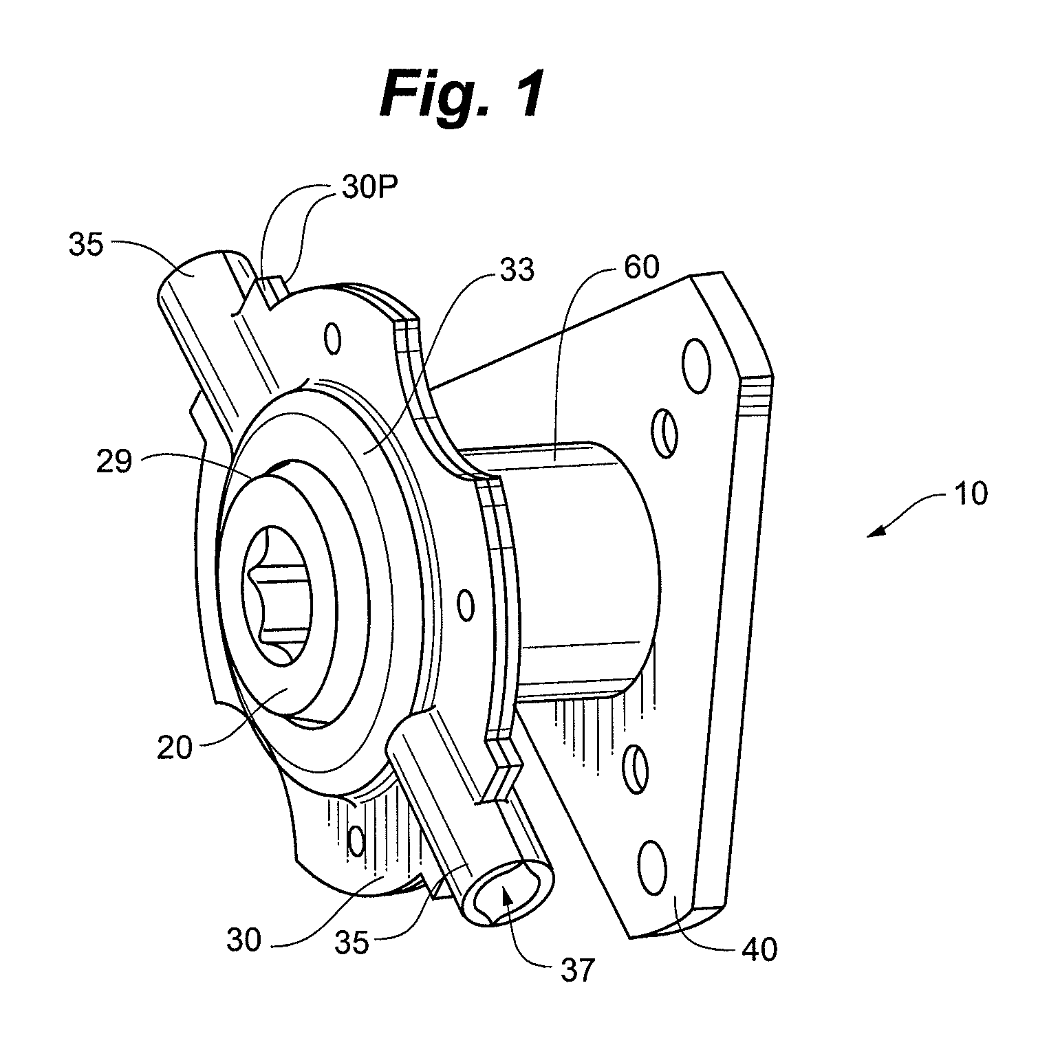
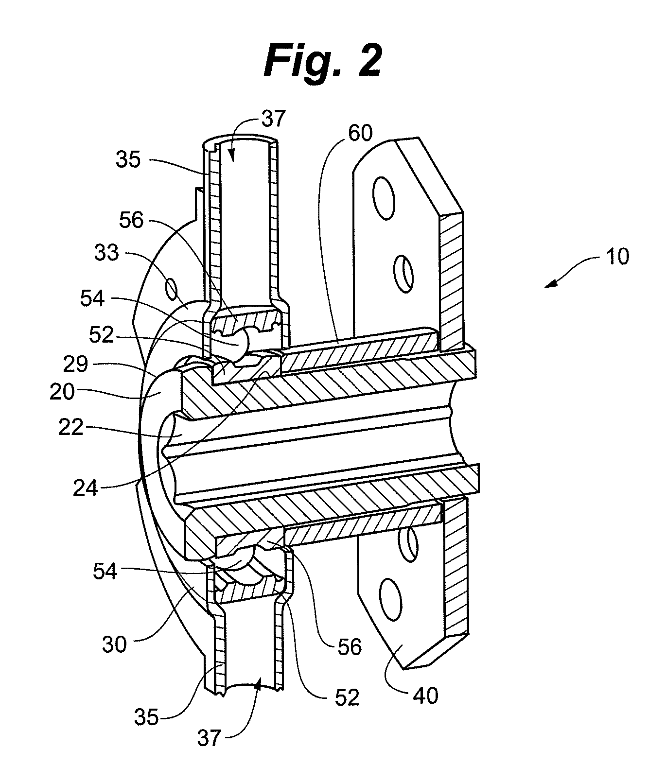
[0022]The invention provides a bearing assembly for the drive system of a snow blower, mower, tractor, or other self-propelled vehicle. The bearing assembly is configured for use in a drive system having a motor flywheel. The bearing assembly facilitates power transmission from the flywheel to at least one driven wheel of the vehicle. There may, of course, be two or more such driven wheels. The vehicle is thus self-propelled.

[0023]Thus, certain embodiments of the invention provide a bearing assembly for the drive unit of a snow blower, mower, tractor, or other self-prope...


PUM


Abstract

The invention provides a trunnion bearing assembly for the drive system of a snow blower, mower, tractor, or other self-propelled utility vehicle. In certain embodiments, the trunnion assembly comprises a bearing having ball bearings, roller bearings, or another type of bearing set. This can provide free relative rotation of several components of the bearing assembly relative to a trunnion housing of the bearing assembly. This rotation is imparted when a friction disk of the assembly engages a spinning motor flywheel of the drive system.

Description

FIELD OF THE INVENTION[0001]The invention relates generally to bearing assemblies. More particularly, the invention relates to a bearing assembly for the drive system of a snow blower, mower, tractor, or other self-propelled utility vehicle.BACKGROUND OF THE INVENTION[0002]Some self-propelled utility vehicles have a drive system in which a trunnion bearing assembly is provided. A conventional trunnion bearing assembly is shown in FIG. 14. Here, the assembly has a bearing encapsulated in a stamped trunnion housing TH and mounted to an inner shaft IS. The trunnion housing is mounted at one end region of the inner shaft and a stamped plate SP is secured (staked) to an opposite end of the shaft. A rubber wheel (not shown) is attached to the stamped plate SP. A hex axle (not shown) is mounted in a hex-shaped internal opening IO of the shaft IS. A shift linkage (not shown) is attached to the trunnion housing TH by virtue of two pins or the like received respectively in two openings OP def...

Claims


Application Information

Patent Timeline
Patent Type & Authority Patents(United States)
IPC IPC(8): B60T1/06
CPCF16C35/045F16C19/06F16C35/063
Inventor STOEHR, KYLE C.BREYER, SCOTT T.
Owner OCONOMOWOC MFG
Why Eureka
Try Eureka