
Storage organizer

a storage organizer and organizer technology, applied in the field of storage organizers, can solve the problems of cluttered desk or area surrounding the computer and related peripherals, lack of facilities, and inconfigurability, and achieve the effect of convenient locating of the second surfa

Inactive Publication Date: 2007-01-23
STEVENS GENE M +1
View PDF49 Cites 46 Cited by
  • Summary
  • Abstract
  • Description
  • Claims
  • Application Information

AI Technical Summary

Benefits of technology

"The invention is a storage organizer for a computer unit that provides organized storage for a wide range of accessories in a small space. The organizer includes a panel with storage cells for storing accessories, which can be placed adjacent to the side surface of the computer unit. The panel can be joined with another panel to provide additional storage space on the other surface of the computer unit. The organizer is designed to be convenient and efficient for operators of the computer."

Problems solved by technology

Typically, however, each such facility provides storage for only a few of the accessories, and requires a dedicated space on a desk top or adjacent planar, and typically horizontal, surface.
Where several such storage facilities are used to organize and store accessories, the desk top or area surrounding the computer and related peripherals becomes cluttered because of the demand for the dedicated spaces.
The storage caddy described in U.S. Pat. No. 3,717,188 does not provide facility for storing the various types of accessories noted above, and is not configured for locating the caddy in a confined space adjacent a computer or peripherals thereof.
An inefficient, time-consuming and thought-interrupting trip by the operator is required to retrieve such distant accessories.
While many operators of computers and peripherals use various types of the above-noted storage facilities, still others do not use any storage facilities, which results in a cluttered and inefficient environment adjacent the computer and the peripherals.

Method used


Image

  • Storage organizer
  • Storage organizer
  • Storage organizer

Examples


Embodiment Construction

[0045]In the following description of a storage organizer, various terms will be used to collectively define certain items associated with computers. The term “computer unit” refers to computer-related facilities such as, for example, computers and computer peripherals, which include, but are not limited to, computers, monitors, speakers, printers, facsimile machines, scanners, copiers and the like. The term “computer accessories” includes, but is not limited to, diskettes, compact disks, optical disks, high-storage disks, back-up tapes, manuals, documents, cables, plugs, special mechanical tools, special cleaning products, writing instruments, stationery, paper clips, binder clips and the like.

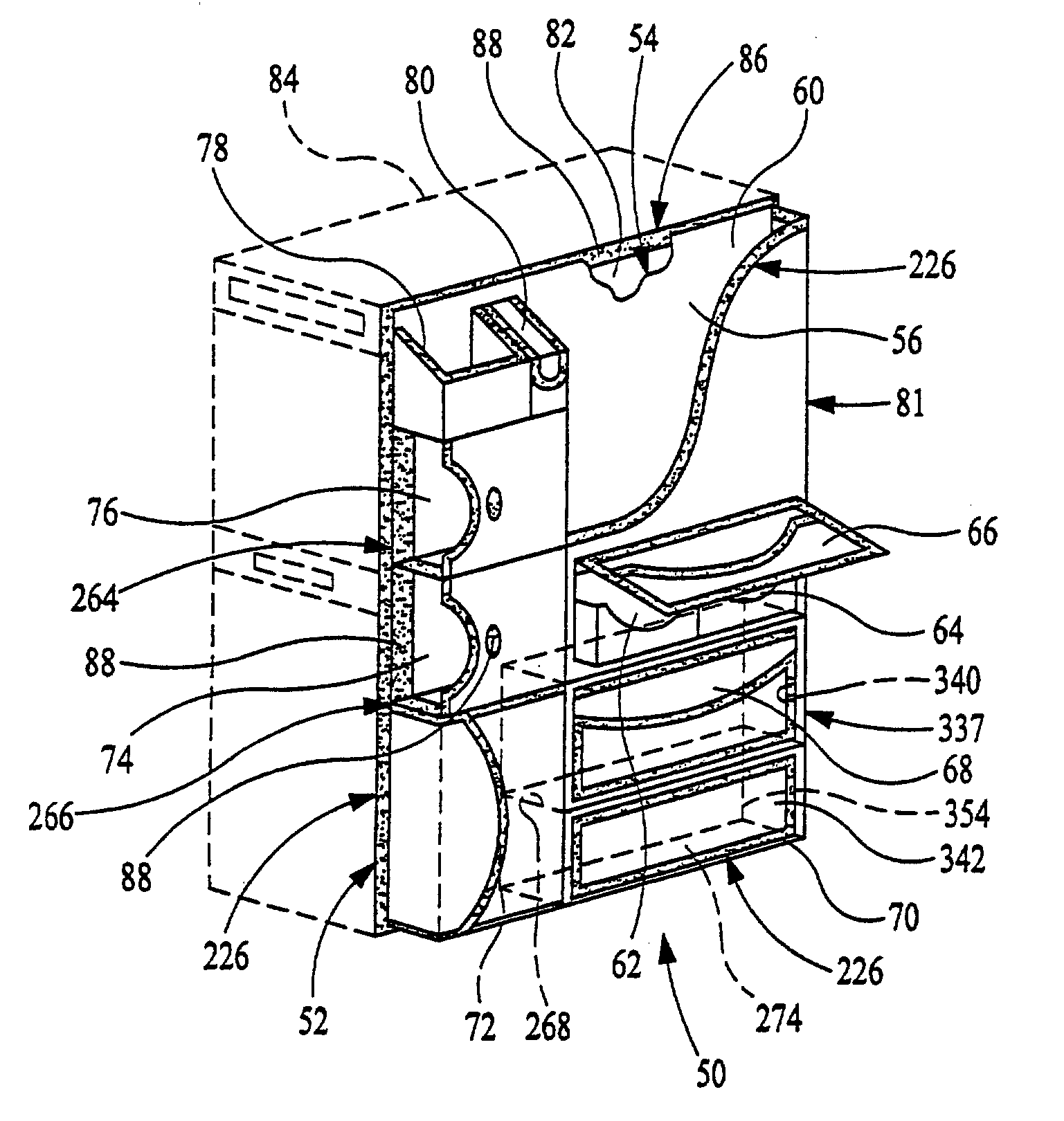
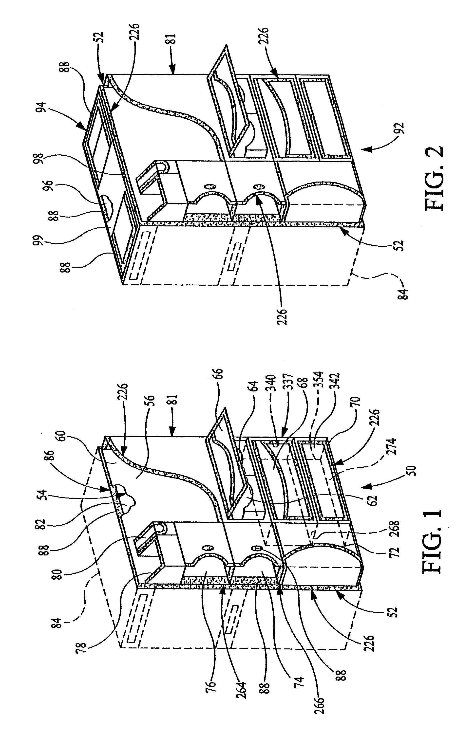
[0046]As shown in FIG. 1, a first embodiment 50 of the storage organizer includes a major, flat, left side panel 52 formed from a panel material 54 (FIG. 13), generally in a square or rectangular shape. The panel 52 is formed with a first major, or outboard, surface 56 and a second major, or ...


PUM


Abstract

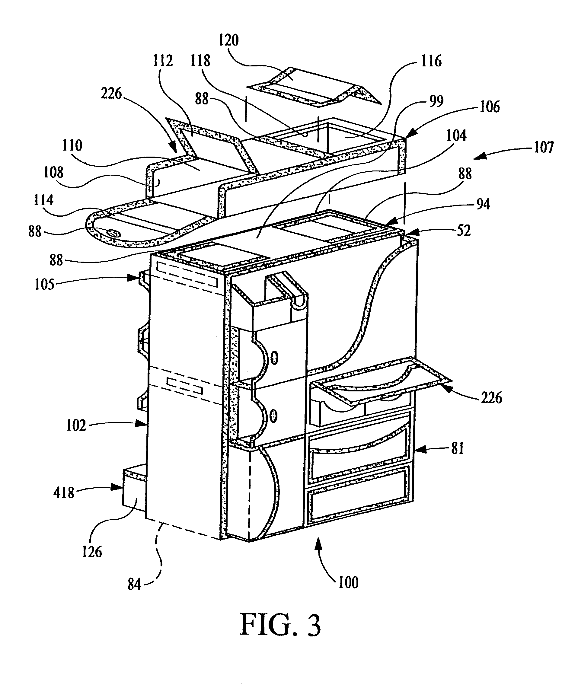
One embodiment (100) of a storage organizer includes three panels (52), (94) and (102) which are structured for attachment by a hook and loop fastener (86) to exterior surfaces of a computer unit including a computer (84). Other panels (81), (105) and (380), and a top storage unit (106), are attached to exterior surfaces of respective ones of the panels (52), (94) and (102). The panels (81), (105) and (380), and the top storage unit (106), are structured to form various configurations of storage cells for storing accessories typically used in conjunction with the use of the computer (84). The panels (52), (81), (94), (102), (105) and (380) are composed of a panel material (54) which includes three layers (216), (218) and (220) of a non-metallic material which are bound together by an edge binder (226) sewn in place by a thread (228).

Description

[0001]This application is a continuation of applicants' U.S. application Ser. No. 09 / 559,706, filed on Apr. 27, 2000 now abandoned, and titled STORAGE ORGANIZER, which is pending. The disclosure of applicants' above-noted co-pending application is incorporated herein by reference thereto.BACKGROUND OF THE INVENTION[0002]This invention relates to a storage organizer, and particularly relates to a storage organizer associated with computers and computer peripherals, and having a plurality of compartments for storing a variety of computer-related accessories.[0003]In recent years, the popularity and demand for personal computers has been increasing at a significantly high rate. Such demand stems from many segments of society including, for example, the workplace, schools and the home. This popularity, in effect, has resulted in the development of many accessories for use with the computer and the peripherals. Examples of such accessories include cables, plugs, diskettes, compact disks,...

Claims


Application Information

Patent Timeline
Patent Type & Authority Patents(United States)
IPC IPC(8): A47F5/00
CPCG06F1/181B42F17/08
Inventor STEVENS, GENE M.STEVENS, JOYSELYN
Owner STEVENS GENE M
Learn More