Multi-fiber optical connect

a fiber optic connection and fiber optic technology, applied in the field of fiber optic systems, can solve the problems of increasing the degree of freedom of both optical connections, affecting the stability of the connection, and the relative stability of the cable end relative to the other, and achieve the effect of stable conta

Active Publication Date: 2007-01-23
HUTCHINSON TECH
View PDF23 Cites 95 Cited by
  • Summary
  • Abstract
  • Description
  • Claims
  • Application Information

AI Technical Summary

Problems solved by technology

The added degrees-of-freedom is generally undesirable for both optical connections that are relatively immobile (such as those for buried optical cables) and those that tend to be flexed or moved often (such as those connecting handheld optical probes to base stations).
However, it is particularly undesirable for the latter as the movement of the connections will more likely expose the connector to impact and cause the connected cable ends to rock or shift relative to one another when the connector is moved.

Method used


Image

  • Multi-fiber optical connect
  • Multi-fiber optical connect
  • Multi-fiber optical connect

Examples


Embodiment Construction

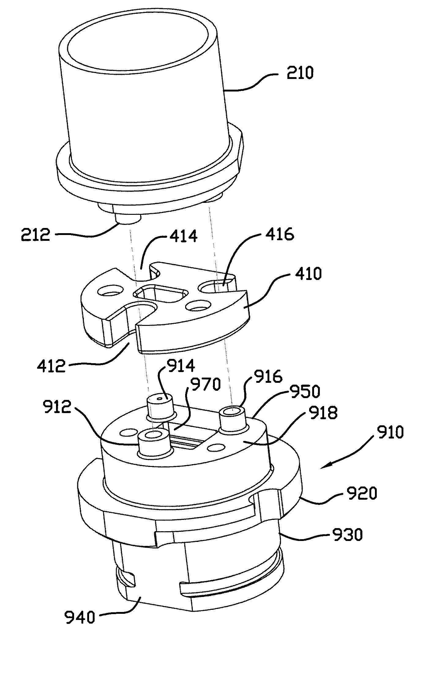
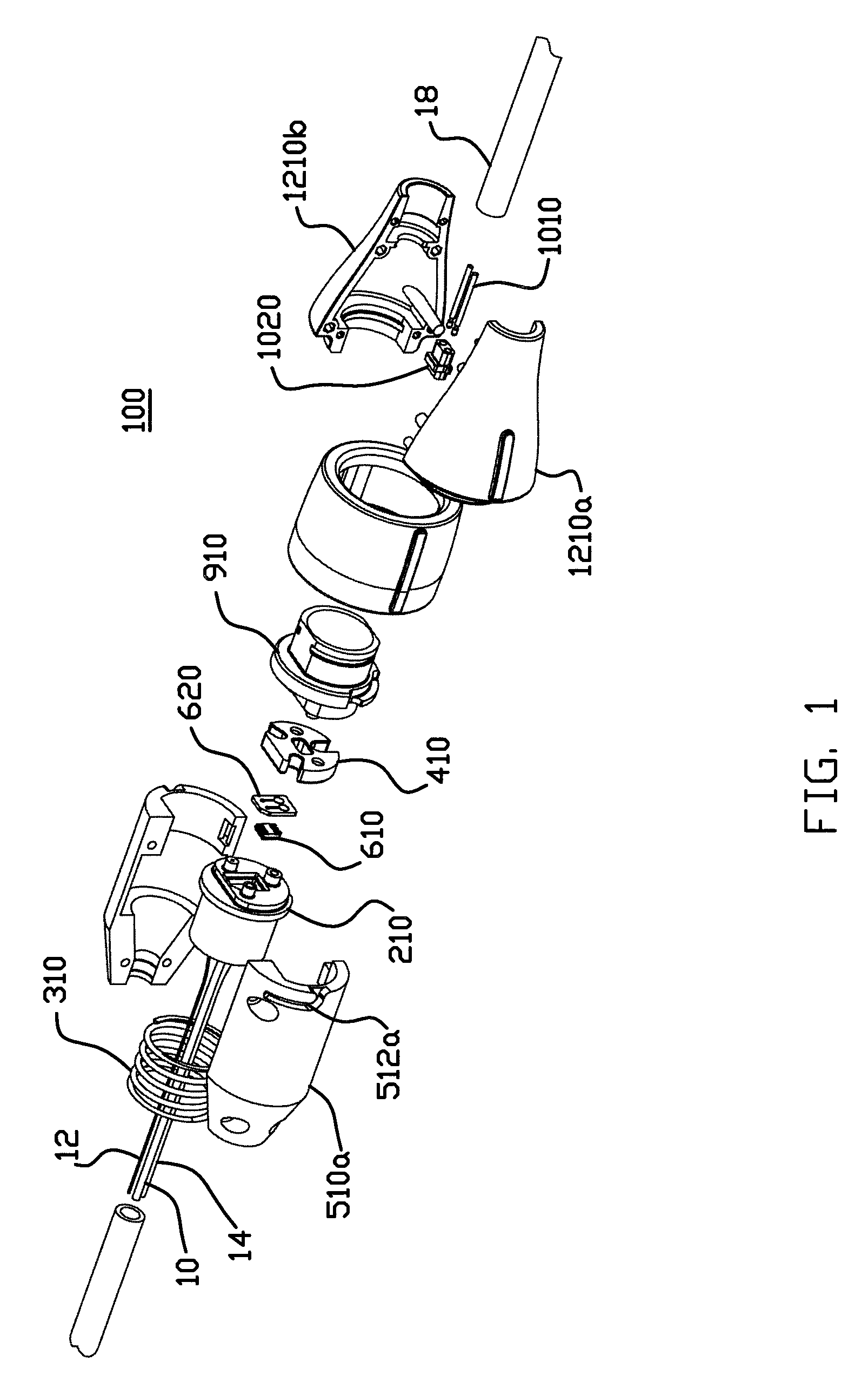
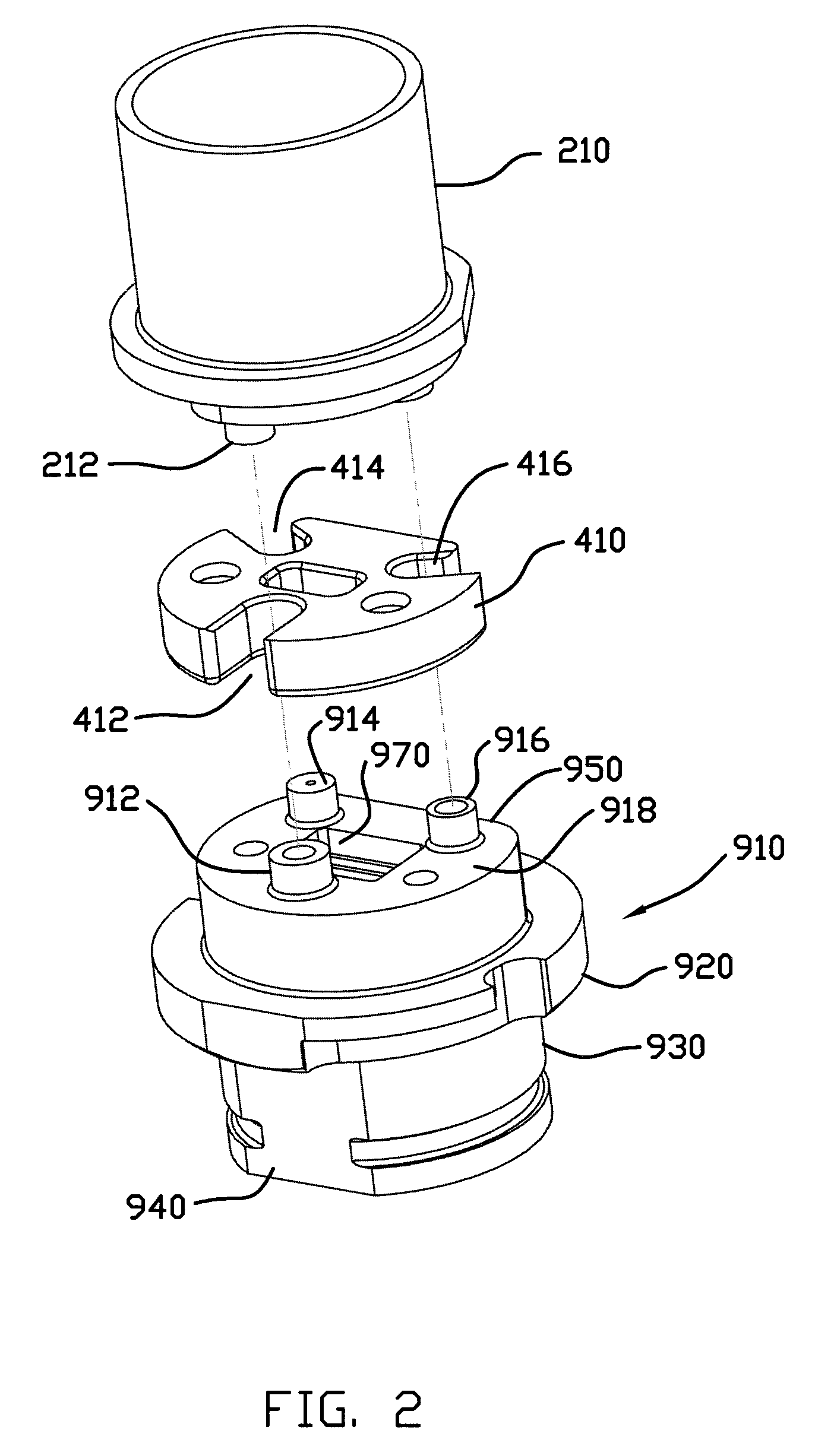
[0029]Referring to FIG. 1, an illustrative embodiment of the invention is a connector 100 for connecting a first set of optical cables 10, 12 and 14 (see also FIG. 4) to a second set of three optical cables (not shown). Each set is enclosed in a protective shield (16 and 18, respectively). The first set of cables extend from the connector 100 to an end optical device (not shown), such as a handheld optical probe for measuring the spectral response characteristics of the subject of investigation (e.g., human tissues). An example of such a probe is disclosed U.S. patent application Ser. No. 10 / 698,751, which is commonly owned with the present application and is incorporated herein by reference. Each optical cable carries a desired number of individual optical fibers. For example, optical cable 10 is an input optical cable for transmitting light of different wavelengths to an optical emitter in the probe and includes a number of (e.g., four) optical fiber bundles 0.75 mm in diameter, e...


PUM


Abstract

An optical connector comprises a first block having a channel for accommodating a first set of optical cables and a second block having a channel for accommodating a second set of optical cables. Each block has three protrusions, each adapted to be engaged to a respective one of the three protrusions from the other block in an end-to-end fashion and having a channel for accommodating one of the optical cables. The connector further comprises a spring biasing the two blocks to maintain the end-to-end engagement a longitudinal direction between the protrusions three spacers. The connector also includes limiter disk having three slots arranged in a Y-pattern, each slot width-wise closely fitting an opposing pair of the protrusions. The limiter disk thus constrains the relative shifting or rotation between the two blocks in any direction transverse to the longitudinal direction. The connector further includes a fastener attached to the two blocks for securing the two blocks together. A kinematic support is thus provided for stable optical connection across an optical connector.

Description

FIELD OF THE INVENTION[0001]The invention relates generally to fiber optical systems. More particularly, the invention relates to an optical connector and method for reliably connecting optical fibers.BACKGROUND OF THE INVENTION[0002]Optical connectors are important components in fiber optical systems. Stable, intimate contacts between optical cables are crucial for reliable transmission of signals across the connection. The ability of two cable ends that are to be secured together by a connector to move relative to one another is often characterized by the degrees-of-freedom one end has relative to another. A cable end totally unconstrained relative to another has six degrees-of-freedom, which are often expressed in terms of three translational and three rotational coordinates. Ideally, the ends being connected have no degree-of-freedom relative to each other.[0003]Optical cables are typically spliced in an end-to-end fashion. The connectors typically are designed to hold the oppos...

Claims


Application Information

Patent Timeline
Patent Type & Authority Patents(United States)
IPC IPC(8): G02B6/38
CPCG02B6/3817G02B6/3821G02B6/40G02B6/3891G02B6/3879
Inventor SCHMITZ, ROGER W.
Owner HUTCHINSON TECH
Why Eureka
Try Eureka