
Intervertebral disk prosthesis or artificial vertebra

a technology of intervertebral disk and prosthesis, which is applied in the field of intervertebral disk prosthesis or artificial vertebra, can solve the problems of low stiffness, considerable risks, and lack of active elastic element that could flexibly absorb loads, and achieve the effect of increasing stiffness

Inactive Publication Date: 2007-01-23
SYNTHES USA
View PDF6 Cites 67 Cited by
  • Summary
  • Abstract
  • Description
  • Claims
  • Application Information

AI Technical Summary

Benefits of technology

[0006]The advantages essentially achieved by the invention are that by virtue of the intervertebral disk prosthesis or the artificial vertebral body the function and the task of an intervertebral disk or of a natural vertebral body can be reproduced as close as possible.
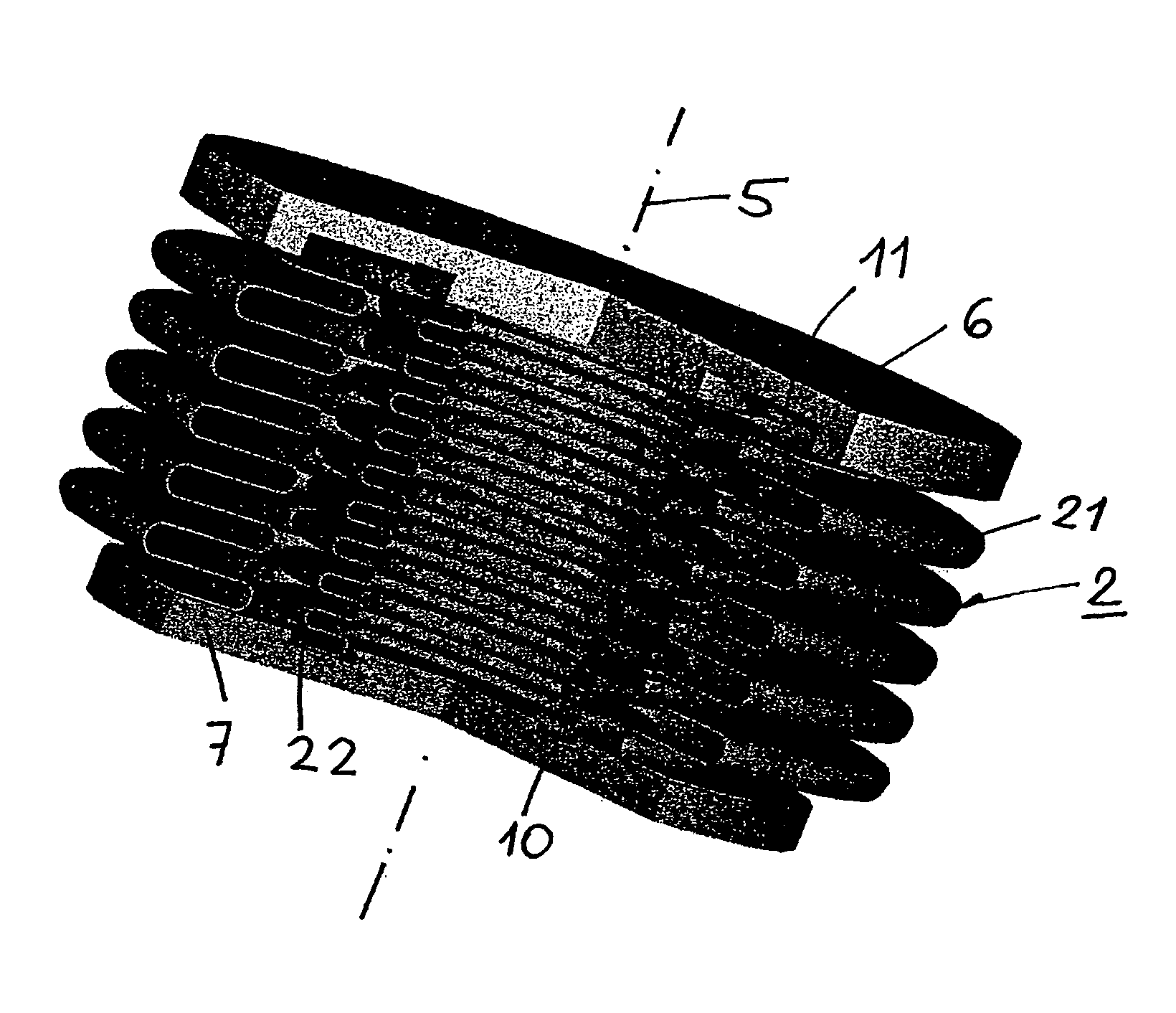
[0014]In the case of a special embodiment the single layers are spaced from one another. By virtue of this construction various bellows can be combined with one another, that can accept various loads, e.g. an external bellows for the angulation, translation, rotation and dampening of a load, for example, 800 N and an internal bellows to accept loads of approx. 2500 N, so that the external bellows will be protected.
[0015]In the case of another special embodiment the single layers abut against one another without intermediate layers. Thus the stiffness can be increased.
[0017]The jacket may also have slots, that should extend basically parallel to the longitudinal axis. By virtue of this the rotational stiffness of the bellows will be reduced.

Problems solved by technology

Thus in the case of this known device it lacks an active elastic element that could flexibly absorb the loads.
In addition, a further disadvantage of this known vertebral body prosthesis is that subsequently it has to be filled with a fluid, e.g. a methacrylate (in particular methyl methacrylate MMA), representing considerable risks.
The disadvantage of this known intervertebral disk prosthesis is its low stiffness.

Method used


Image

  • Intervertebral disk prosthesis or artificial vertebra
  • Intervertebral disk prosthesis or artificial vertebra
  • Intervertebral disk prosthesis or artificial vertebra

Examples


Embodiment Construction

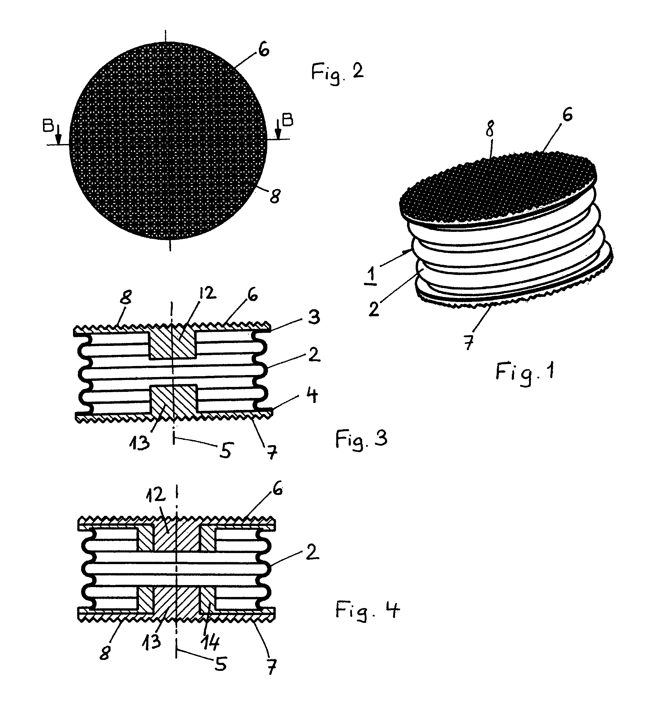
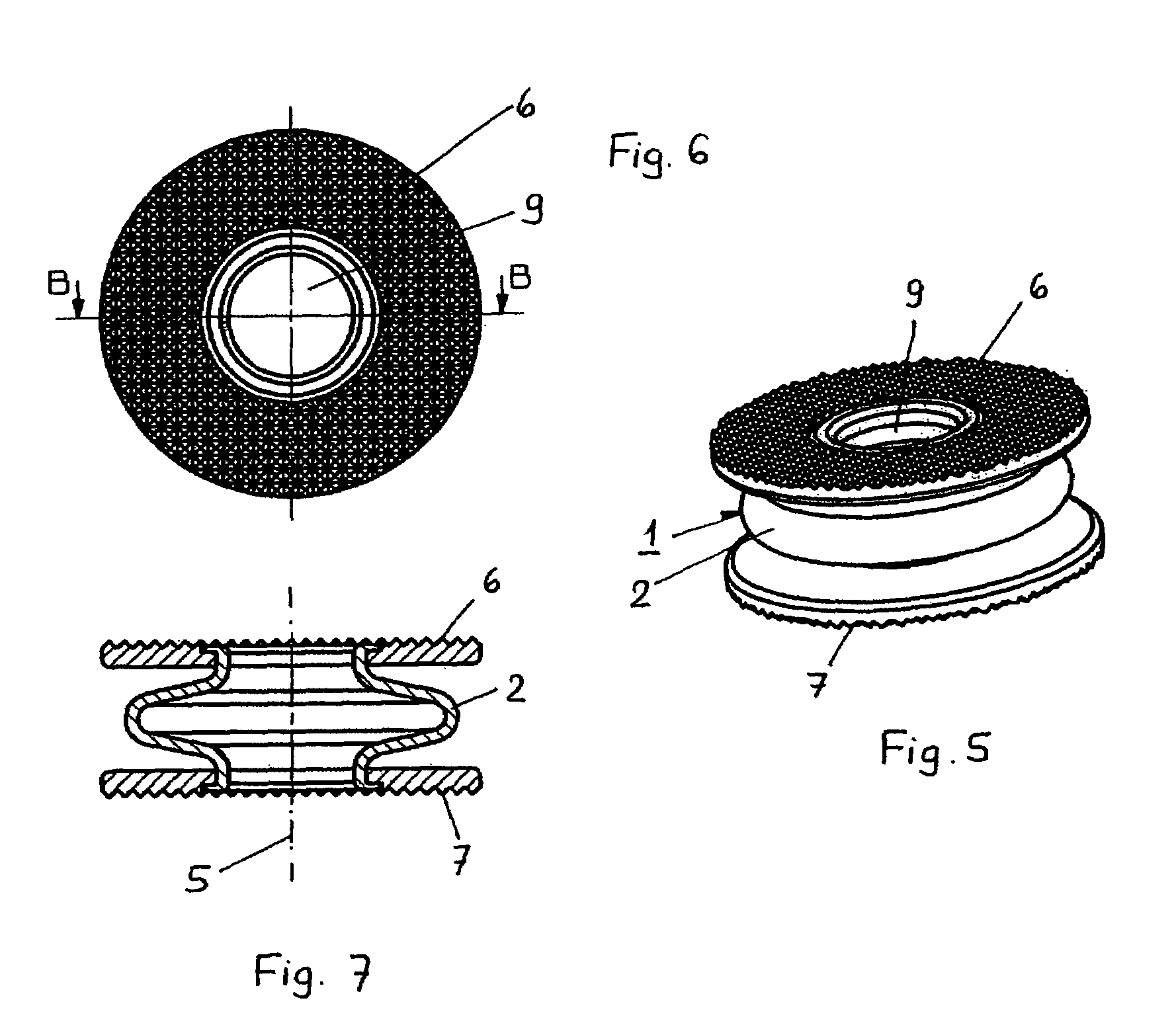
[0038]The intervertebral disk prosthesis, illustrated in FIGS. 1–3, essentially comprises a hollow-cylindrical basic body 1 with a jacket 2 constructed as a bellows, a top end 3, a bottom end 4 and a central longitudinal axis 5. On the top end 3 of the basic body 1 a top apposition plate 6 is provided transversely to the longitudinal axis 5, that is intended as a support for the base plate of a vertebral body. On the bottom end 4 of the basic body 1 a bottom apposition plate 7 is provided transversely to the longitudinal axis 5, that can be placed on the cover plate of a vertebral body.

[0039]Both apposition plates 6, 7 have an outwardly structured surface 8, that is made up from a plurality of pyramid-shaped teeth, so that to achieve a better contact with the base and cover plates of the adjacent vertebral bodies. The structured surface 8 can be also realised in the form of etching the surface or in the form of surface structures promoting the adherence of the bone tissue.

[0040]The ...


PUM


Abstract

An intervertebral disk prosthesis having an essentially hollow cylindrical base element (1) which is provided with a casing (2) that is embodied as a bellows, a top end (3), and a bottom end (4), and a central longitudinal axis (5). The base element also includes an upper apposition plate (6), which is disposed perpendicular to the longitudinal axis (5) at the top end (3) of the base element (1) and rests on the base plate of the vertebra, and a lower apposition plate (7), which is arranged perpendicular to the longitudinal axis (5) at the bottom end (4) of the base element (1) and leans on the cover plate of a vertebra. The casing (2) serves a spring element having a defined spring rate.

Description

BACKGROUND OF THE INVENTION[0001]The invention concerns an intervertebral disk prosthesis or an artificial vertebral body.[0002]From U.S. Pat. No. 4,932,975 Main et al. a vertebra prosthesis is known, that comprises an expandable bellows as the basic body. The bellows is made from a flexible material, that allows an expansion of the bellows. However, in the case of this bellows basically one deals with a passive element, that through an opening can be filled with a fluid, while the bellows passively stretches. Thus in the case of this known device it lacks an active elastic element that could flexibly absorb the loads. In addition, a further disadvantage of this known vertebral body prosthesis is that subsequently it has to be filled with a fluid, e.g. a methacrylate (in particular methyl methacrylate MMA), representing considerable risks.[0003]From WO 00 / 35383 Dimso, an intervertebral disk prosthesis of the generic type is known. This known intervertebral disk prosthesis comprises ...

Claims


Application Information

Patent Timeline
IPC IPC(8): A61F2/44A61F2/00A61F2/30
CPCA61F2/44A61F2/442A61F2002/30136A61F2002/30365A61F2002/30563A61F2002/30565A61F2310/00023A61F2002/30594A61F2002/30841A61F2002/443A61F2002/4475A61F2220/0033A61F2230/0004A61F2002/3057A61F2002/30568A61F2002/30593
Inventor STUDER, ARMINTRACHSEL, JASONWYMANN, MARTIN
Owner SYNTHES USA
Learn More