Energy recovering apparatus and method for plasma display panel

a technology of energy recovery apparatus and plasma display panel, which is applied in the direction of lighting apparatus, instruments, light sources, etc., can solve the problems of high manufacturing cost, complex circuit configuration, and large power consumption caused by a plurality of switch conduction loss, and achieve the effect of rapid rising tim

Inactive Publication Date: 2007-01-23
LG ELECTRONICS INC
View PDF12 Cites 12 Cited by
  • Summary
  • Abstract
  • Description
  • Claims
  • Application Information

AI Technical Summary

Benefits of technology

[0038]Accordingly, it is an object of the present invention to provide an energy recovering apparatus and method for a plasma display panel that is capable of supplying a sustain pulse having a rapid rising time.
[0049]Said (B) step includes forming a path between the panel and the second voltage source going by way of the first inductor using a second switch connected between the first inductor and the panel to thereby recover an energy of the panel into the second voltage source.

Problems solved by technology

However, such conventional energy recovering apparatus 30 and 32 have a problem in that the first energy recovering apparatus 30 provided at the first electrode (Y) side and the second energy recovering apparatus 32 provided at the second electrode (Z) side operate individually to require many circuit elements such as a switching device, etc., and thus to raise a manufacturing cost.
Furthermore, a lot of power consumption is caused by a conduction loss of a plurality of switches, such as a diode, a switch device and an inductor, etc., on the current path.
However, the energy recovering apparatus suggested by U.S. Pat. No. 5,679,094 of NEC corporation requires an energy recovering circuit and a sustain circuit for each of the scanning electrode and the sustain electrode of the plasma display panel 1 to thereby cause a complex circuit configuration.
Accordingly, it has a problem in that a manufacturing cost rises.
Furthermore, a conduction loss of a plurality of switches on the current path in the energy recovering apparatus suggested by U.S. Pat. No. 5,679,094 is smaller than that in the energy recovering apparatus suggested by U.S. Pat. No. 5,081,400, but causes a lot of power consumption due to the conduction loss of the switches.

Method used


Image

  • Energy recovering apparatus and method for plasma display panel
  • Energy recovering apparatus and method for plasma display panel
  • Energy recovering apparatus and method for plasma display panel

Examples


Embodiment Construction

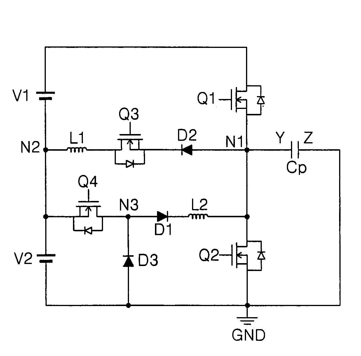
[0070]Referring to FIG. 7, there is shown an energy recovering apparatus of a plasma display panel (PDP) according to the embodiment of the present invention.

[0071]The energy recovering apparatus includes a panel capacitor Cp that is an equivalent capacitance formed between first and second electrodes Y and Z of the PDP, first and second voltage sources V1 and V2 connected in series, a first inductor L1 connected between a first node N1 connected to the first electrode Y and a second node N2 between the first and second voltage sources V1 and V2, a second inductor L2 connected between the first node N1 and the second node N2 and, at the same time, connected, in parallel, to the first inductor L1, first and second switches Q1 and Q2 connected, in parallel, to the panel capacitor Cp with having the first node N1 therebetween, a third switch Q3 connected between the first inductor L1 and the first node N1, a fourth switch Q4 connected between the second node N2 and the second inductor ...


PUM


Abstract

An energy recovering apparatus and method for a plasma display panel that is capable of supplying a sustain pulse having a rapid rising time. In the apparatus and method, a voltage source supplies a sustain voltage to the panel. A first inductor recovers an energy stored in the panel into the voltage source, and a second inductor receives energy from the voltage source in which the recovered energy has been stored to charge the received energy. Switching devices shuts off a path between the voltage source and the second inductor in a state in which energy has been stored in the second inductor to derive an inverse voltage into the second inductor and allows said inverse voltage to be applied to the panel.

Description

BACKGROUND OF THE INVENTION[0001]1. Field of the Invention[0002]This invention relates to an energy recovering apparatus and method for a plasma display panel, and more particularly to an energy recovering apparatus and method for a plasma display panel that is capable of supplying a sustain pulse having a rapid rising time.[0003]2. Description of the Related Art[0004]Recently, there has been developed various flat panel devices that are capable of reducing a heavy weight and a large bulk, which are drawbacks of the cathode ray tube (CRT). Such flat panel display devices include a liquid crystal display (LCD), a field emission display (FED), a plasma display panel (PDP) and an electro-luminescence display (ELD), etc.[0005]The PDP of these flat panel display devices is a display device using a gas discharge, and has an advantage in that it is easy to manufacture a large-dimension panel. The PDP typically includes a three-electrode, alternating current (AC) surface discharge PDP that ...

Claims


Application Information

Patent Timeline
Patent Type & Authority Patents(United States)
IPC IPC(8): G09G3/10G09G3/28G09G3/288H05B41/14
CPCG09G3/2965G09G3/2942G09G3/296
Inventor CHO, JANG HWANYOON, WON SIK
Owner LG ELECTRONICS INC
Why Eureka
Try Eureka