
Laser apparatus such as a construction laser apparatus

a laser and laser technology, applied in lasers, laser construction details, active open surveying means, etc., can solve the problems of affecting the inability to adjust the housing only in the vertical direction, and the relatively high cost of crank-operated columns, so as to achieve the effect of ensuring the protection of the laser

Active Publication Date: 2007-01-23
STABILA MESSGERATE GUSTAV ULLRICH GMBH & CO KG
View PDF9 Cites 16 Cited by
  • Summary
  • Abstract
  • Description
  • Claims
  • Application Information

AI Technical Summary

Benefits of technology

[0009]The present invention is to solve the problem of modifying a laser apparatus of the aforementioned type in such a manner that on one hand better protection of the apparatus is ensured, and that on the other hand adjustment of the housing, and hence the laser plane, is possible by means of simple design measures.
[0011]Therefore, in accordance with the invention herein, the housing which encloses the light source is, in turn, enclosed by a type of second housing or frame configured as a receiving means, thus providing added protection. At the same time, this receiving means offers the option of adjusting the housing in its longitudinal direction so that, depending on the position of said receiving means relative to a stand, for example, a vertical or horizontal adjustment of the housing is possible, without requiring an adjustment to the stand itself. Furthermore, this does not require a crank-operated central column.
[0015]In particular, the mounting support consists of a shell having the shape of a hollow cylinder which represents the external section and of an insert accommodating the housing which represents the internal section provided with noses which extend in the direction of the housing for engagement in a preferably peripherally extending recess, such as a groove of the spherical section or cap-shaped section of the housing, in order to permit a rotation of the housing about its longitudinal axis without creating the risk of tipping over the apparatus.
[0019]Independent thereof, each bracket has the geometric configuration of a U-shape with lateral legs extending from the base plate and with a transverse leg following a circular arc. In doing so, at least one cushioning element, such as a rubber element, may extend from or enclose the transverse leg, which provides cushioning of shock-like effects which occur when the laser apparatus is dropped.

Problems solved by technology

Crank-operated columns have the disadvantage that they are relatively expensive.
Furthermore, there is the disadvantage that the housing can be adjusted only in vertical direction but not horizontally.
It has been found that, in particular when used on construction sites, a laser apparatus may be damaged by being inadvertently tipped over, even if the laser housing consists of metal.

Method used


Image

  • Laser apparatus such as a construction laser apparatus
  • Laser apparatus such as a construction laser apparatus
  • Laser apparatus such as a construction laser apparatus

Examples


Embodiment Construction

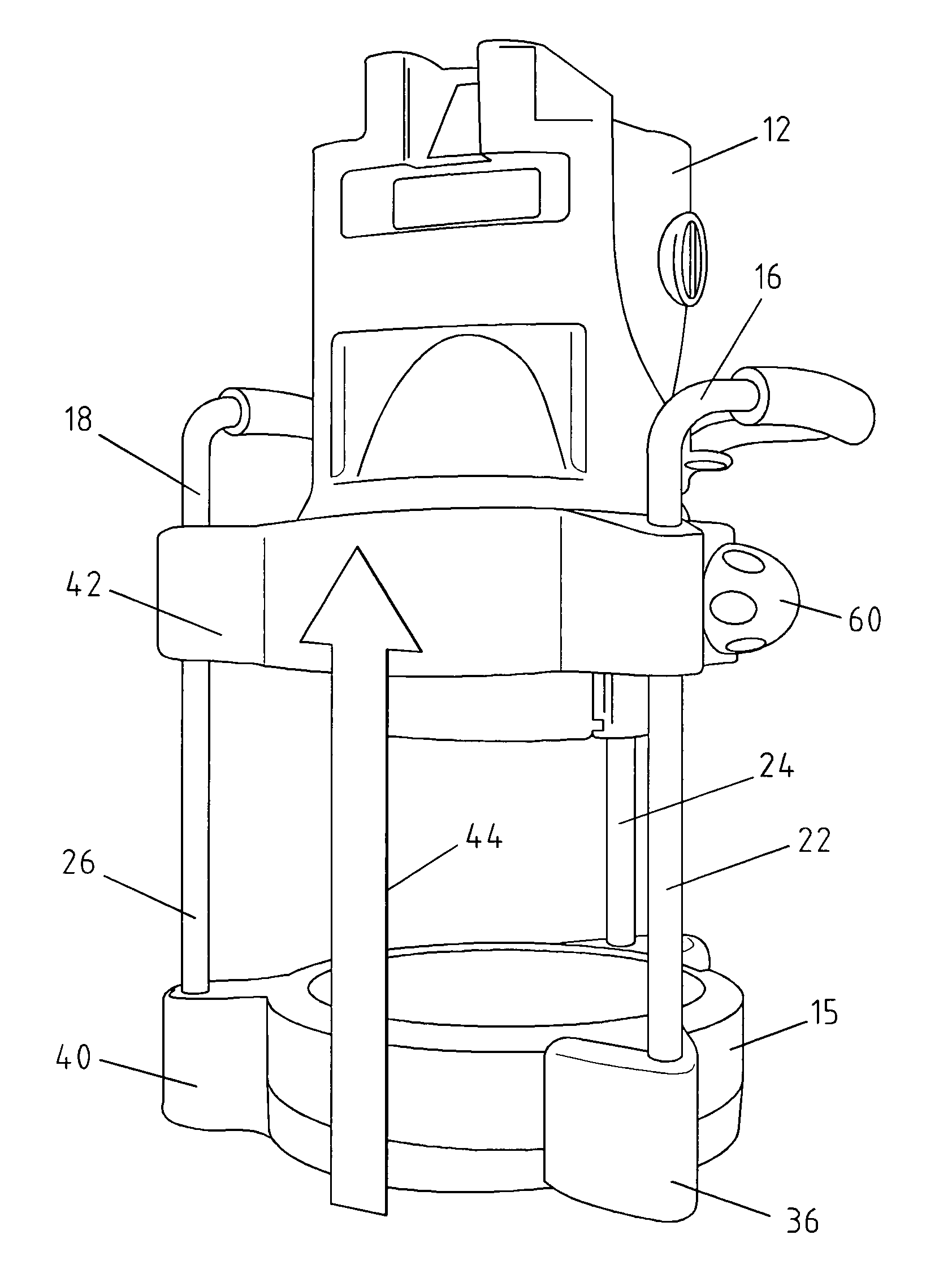
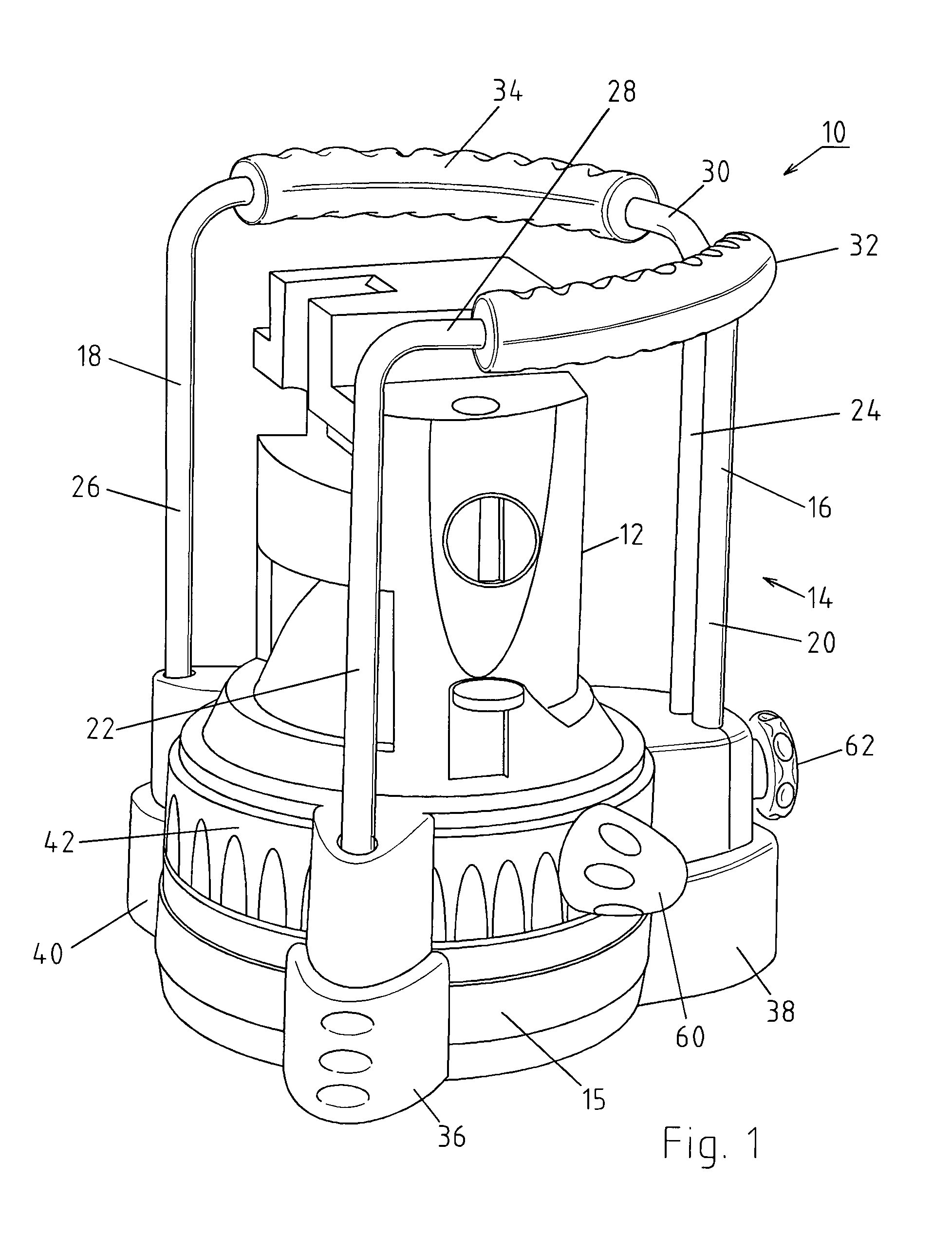
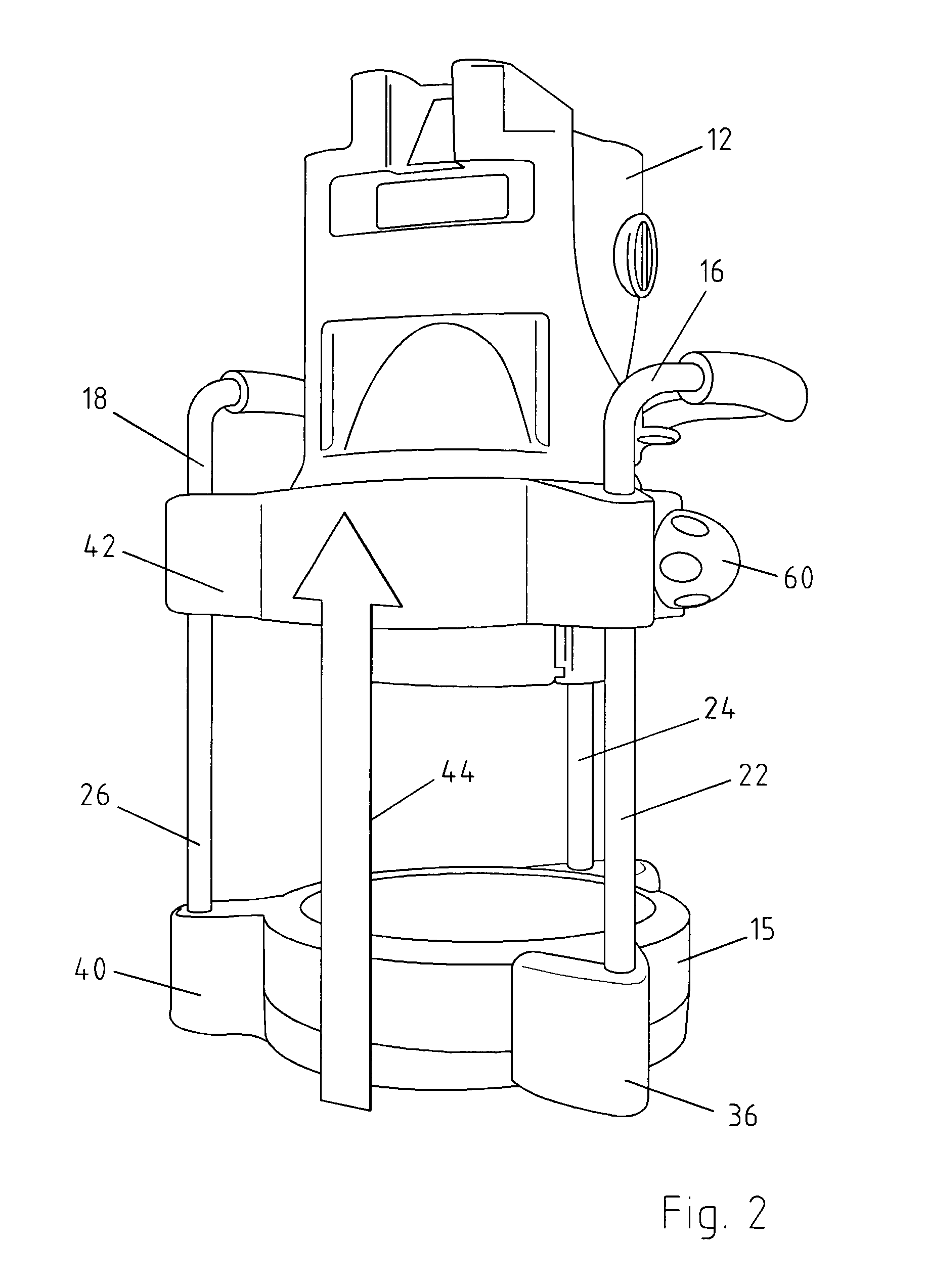
[0034]FIG. 1 shows a laser apparatus 10 in the form of embodiment of a construction laser apparatus—hereinafter referred to as a construction laser—which comprises a housing 12 accommodating a light-emitting laser. In order to protect housing 12, said housing is enclosed by a frame described as a receiving means 14 as shown by the example of embodiment of FIGS. 1 through 4, in order to protect housing 12 when construction laser 10 tips over, for example.

[0035]Receiving means 14 consists of a base plate 15 with U-shaped brackets 16, 18 extending from said base plate. In doing so, each bracket 16, 18 consists of two longitudinal legs 20, 22 and 24, 26, as well as of a transverse leg 28, 30 following a circular arc, whereby, in the example of embodiment, said legs are enclosed by shock-absorbing elements such as rubber elements 32, 34. Said elements themselves are structured and, consequently, may function as handles.

[0036]Support feet which, in turn, are also enclosed by shock-absorbi...


PUM


Abstract

The invention relates to a laser apparatus as construction laser apparatus (10) comprising a light source accommodated inside a housing (12). For providing an increased protection of the apparatus and for adjusting the housing and thus the laser plane to the desired extent with constructive simple measurements, it is suggested that the housing (12) is enclosed by a receiving means (14), along which said housing (12) of the laser is arranged in adjustable manner.

Description

[0001]The invention herein relates to a laser apparatus, such as a construction laser apparatus, comprising a light source accommodated inside a housing.BACKGROUND OF THE INVENTION[0002]Construction laser apparatus—also referred to as construction lasers—can be used to exactly determine lines extending along the appropriate planes on buildings, for example, on ceilings or walls, or in rooms. Such construction lasers comprise a housing accommodating a laser for the emission of light to create lines or dots. In doing so, the laser beam may optionally be emitted in a rotating manner, for example, with the use of a prism.[0003]Frequently, it is necessary to bring the light emitted by the laser to a predetermined intensity level in order to transfer existing projection marks or to achieve a fixed-distance measurement for simple manipulation. To do so, the height adjustment may be achieved by placing the housing of the laser on the crank-operated center column of a stand. Crank-operated c...

Claims


Application Information

Patent Timeline
IPC IPC(8): H01S3/08G01C15/00G01B11/14H01S3/02
CPCG01C15/004G01B11/14
Inventor KALLABIS, GABRIEL
Owner STABILA MESSGERATE GUSTAV ULLRICH GMBH & CO KG
Learn More