
Cable support apparatus for a raised floor system

a cable support and raised floor technology, applied in the direction of mechanical devices, machine supports, other domestic objects, etc., can solve the problems of not being able to accommodate the vast amount of cable runs required, maintaining organization, and additional labor required to assemble the various components of the separate raised floor and cable support system

Inactive Publication Date: 2007-01-30
JETTE ROGER
View PDF40 Cites 41 Cited by
  • Summary
  • Abstract
  • Description
  • Claims
  • Application Information

AI Technical Summary

Benefits of technology

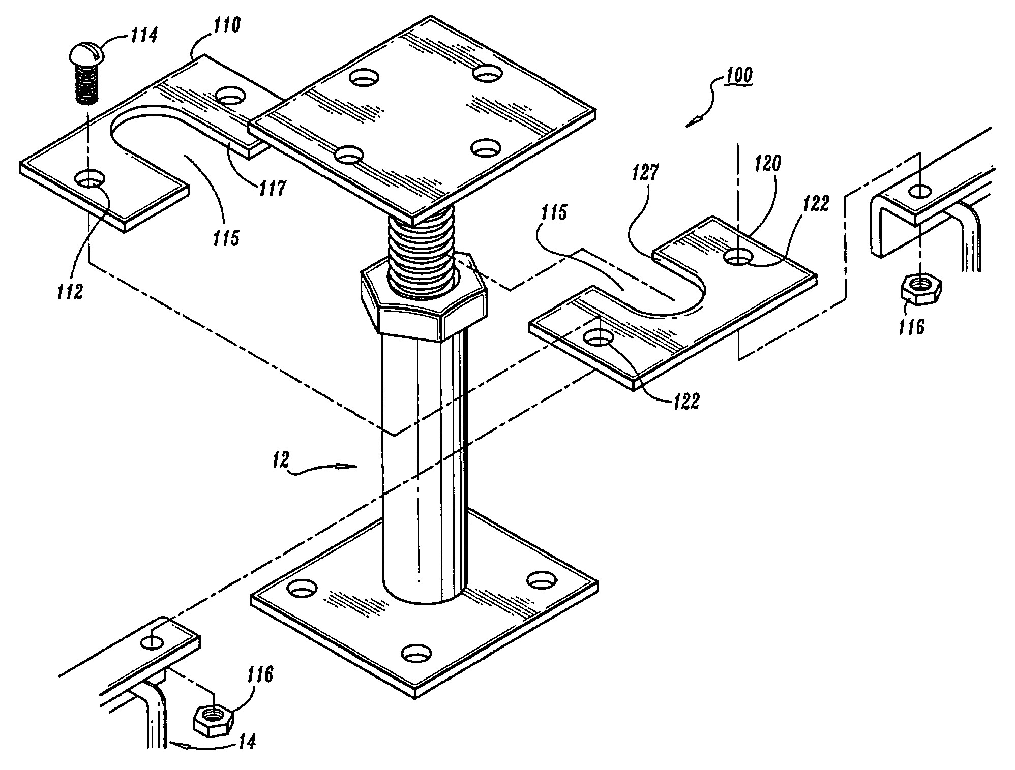
[0012]A cable support apparatus for a raised floor system comprising at least one support member wherein each support member defines at least one slot for positioning on a support pedestal of a raised floor system. The support member being structurally supported by the support pedestal and the support member further defining a plurality of holes therein for the positioning and supporting of at least one cable basket. In one preferred embodiment, the at least one support member includes a first member and a second member. Each member defines a slot configured and dimensioned to engage with the pedestal of the support member and defines at least two holes for connecting with cable trays.

Problems solved by technology

Such installations were typically made in facilities which simply were not designed to accommodate the vast amount of cable runs required to operate the typical large computer system.
A common problem experienced in utilizing raised floor systems is maintaining organization of the various cables, conduits, pipes, etc. which are routed beneath the floor system.
One drawback of such a raised floor and cable support system is the additional labor required to assemble the various components of the separate raised floor and cable support systems.
In geographic regions with particularly high labor rates, the cost of erecting such a labor intensive dual system could prove to be cost prohibitive.
Another drawback of such a system is that a manufacturer's raised floor system typically will only interrelate with and provide support for that manufacturer's cable support system.
Thus, consumers are forced to retrofit or choose a less favorable system in one aspect, such as the raised floor system, over another aspect, such as the cable support system.
In the alternative, independent cable support systems are procured which significantly add the overall costs because materials have to be procured for a separate independent cable support structure.
These additional labor and material costs can significantly increase the overall cost of installing a complete cable support apparatus and raised floor system.
One disadvantage of such a system is the labor intensive nature of the installation.
This combined with the cost of the material components required for such a system can add significant cost to the installation of the complete system.

Method used


Image

  • Cable support apparatus for a raised floor system
  • Cable support apparatus for a raised floor system
  • Cable support apparatus for a raised floor system

Examples


Embodiment Construction

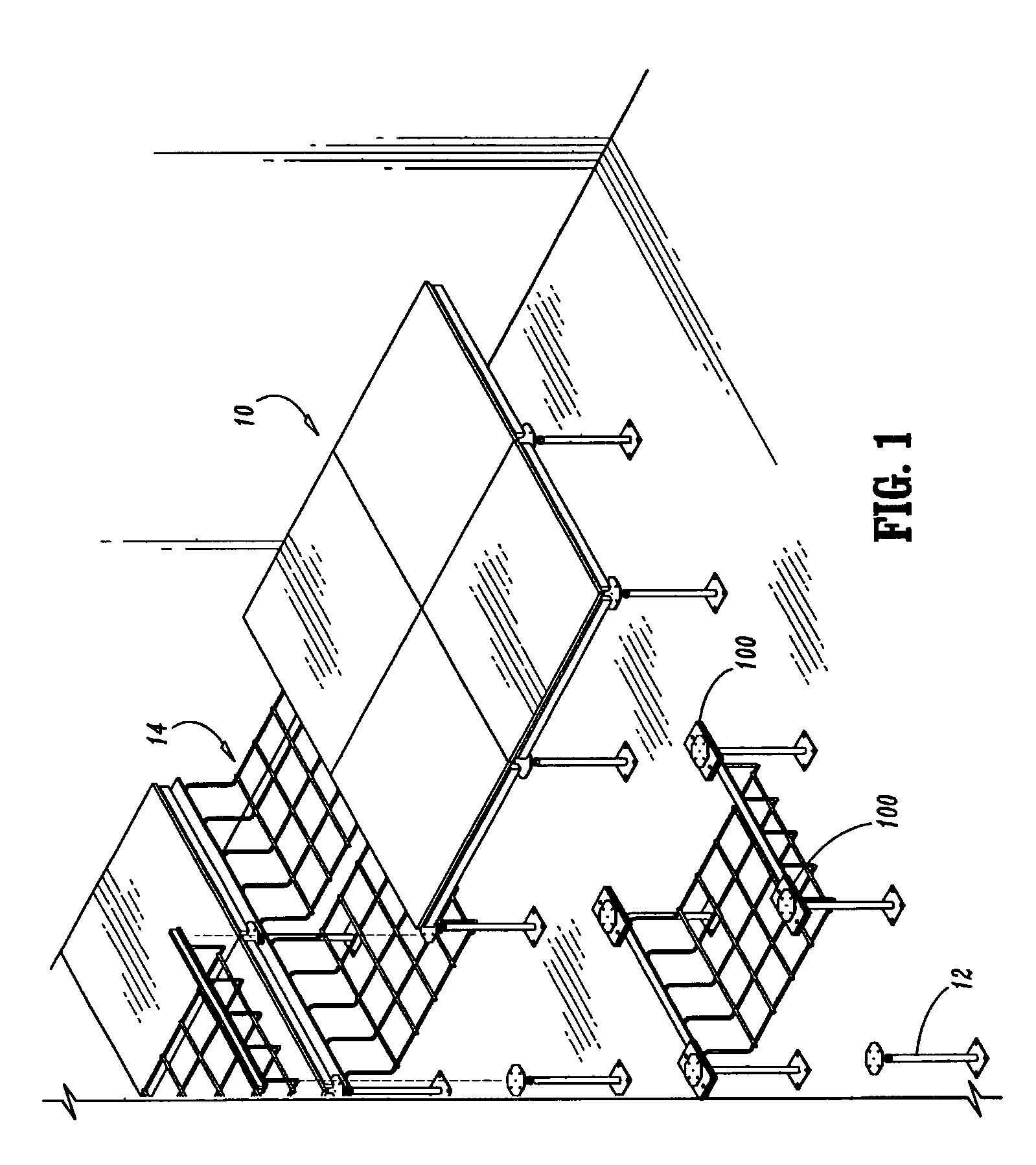
[0021]Referring to the drawings in detail, and initially to FIG. 1, the presently disclosed cable support apparatus for a raised floor system 100 (hereinafter referred to as the “support apparatus 100”) is shown installed on a plurality of support pedestals 12 of a raised floor system 10. Support apparatus 100 is positioned to provide structural support for one or more portions of a cable management system or cable supporting pathways, such as cable baskets 14.

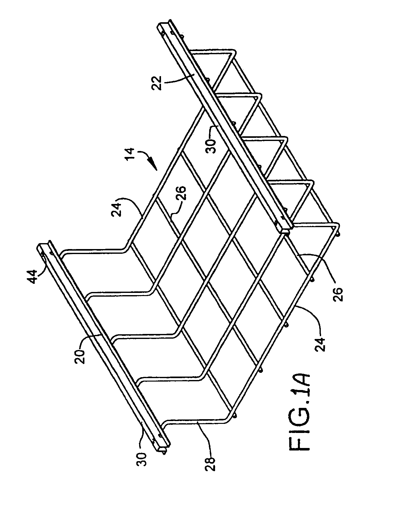
[0022]Referring now to FIG. 1A, cable basket 14 includes first and second elongated stringer elements 20 and 22, respectively. A channel section is suspended from stringers 20 and 22 so as to form a portion of a passageway for supporting cable runs thereon. In the illustrated embodiment, the channel section is formed of an open ended wire stock basket having longitudinal sections 26 attached to transverse sections 24. Transverse sections 24 include riser portions or legs 28 which are attached to the underside of stringers 20 a...


PUM


Abstract

A cable support apparatus for a raised floor system comprising at least one support member. The at least one support member is configured to be mounted to a pedestal of the raised floor system and connect with portions of cable trays. The support member, in one preferred embodiment includes a first member and a second member, each defining a slot for positioning on the support pedestal. The support member also includes a plurality of holes for the securing of the first member and the second member together as well as for connecting with cable trays. The cable trays are attached to the support member with an attachment mechanism such as a threaded stud.

Description

CROSS REFERENCE TO RELATED APPLICATIONS[0001]The present disclosure is a Continuation Application which claims the benefit of and priority to U.S. application Ser. No. 09 / 706,634, filed Nov. 6, 2000, now U.S. Pat. 6,463,704, which claims the benefit of and priority to U.S. Provisional Application No. 60 / 163,910, filed Nov. 5, 1999, the entire contents of each of which being incorporated herein by reference. The present disclosure is also related to applicant's prior U.S. Pat. No 5,953,870 Raised floor System and Cable Support Apparatus, filed Sep. 11, 1997, the entire contents of which are hereby incorporated by reference.BACKGROUND OF INVENTION[0002]1. Technical Field[0003]The present disclosure relates to an apparatus used with a raised floor system for providing a supporting structure for a cable management system and more particularly to a cable support apparatus which can be installed on a support pedestal of the raised floor system to provide structural support for the cable m...

Claims


Application Information

Patent Timeline
Patent Type & Authority Patents(United States)
IPC IPC(8): E04C2/52E04F15/024
CPCE04F15/02458
Inventor JETTE, ROGER
Owner JETTE ROGER
Learn More