Device and method for securing a punch tool to a ram portion of a press brake

Active Publication Date: 2007-01-30
PELECH BRUNO J
View PDF6 Cites 39 Cited by
  • Summary
  • Abstract
  • Description
  • Claims
  • Application Information

AI Technical Summary

Benefits of technology

[0007]It is an object of the present invention to overcome many of the disadva

Problems solved by technology

Punch tools and dies can be relatively long and expensive portions of tool steel.
A problem occurs when the ram portion of the press brake is improved, replaced, revised or retrofitted such

Method used


Image

  • Device and method for securing a punch tool to a ram portion of a press brake
  • Device and method for securing a punch tool to a ram portion of a press brake
  • Device and method for securing a punch tool to a ram portion of a press brake

Examples


Example

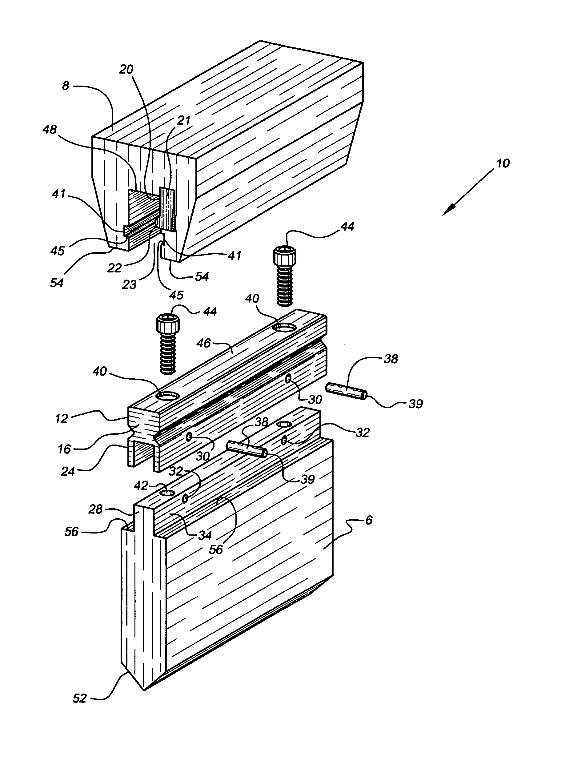
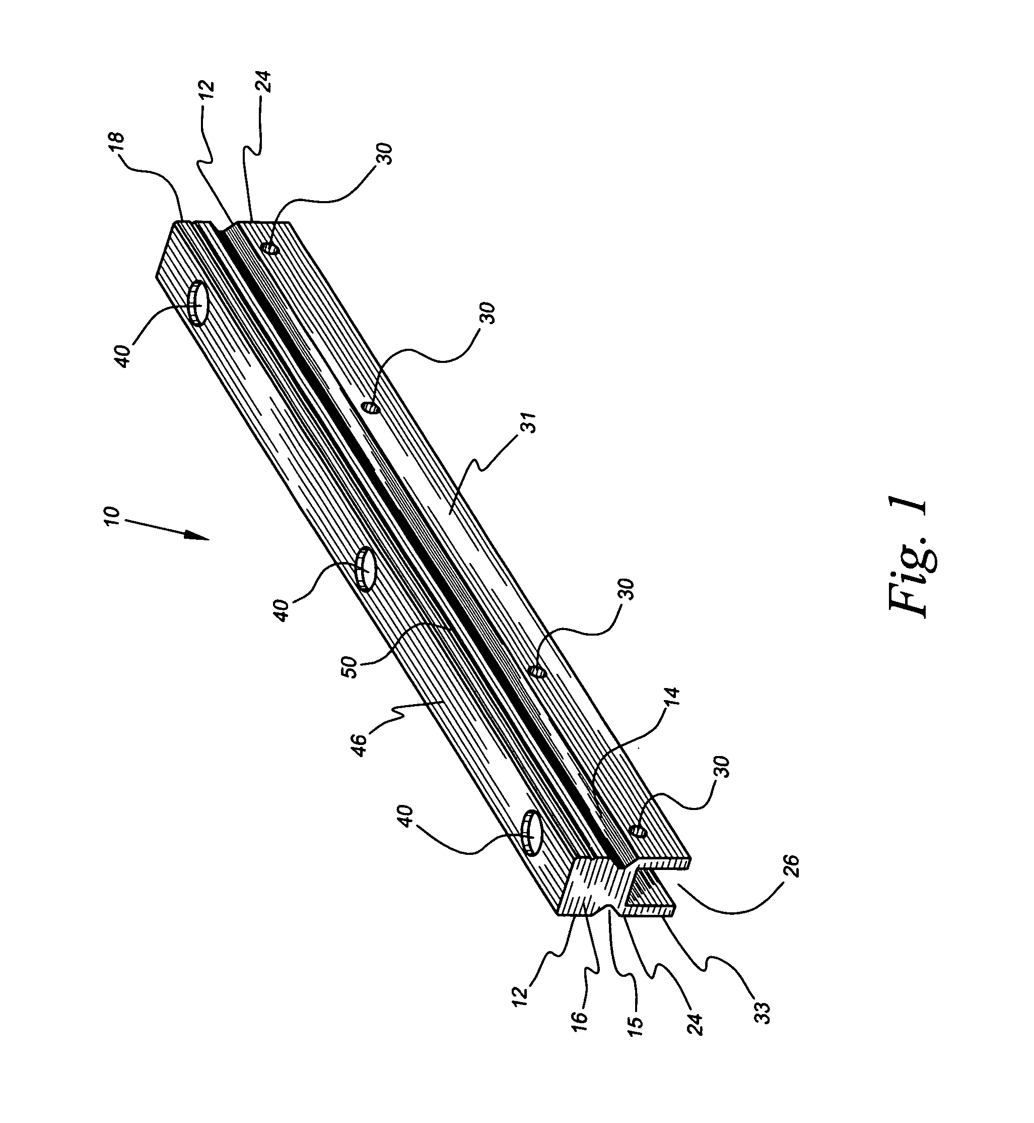
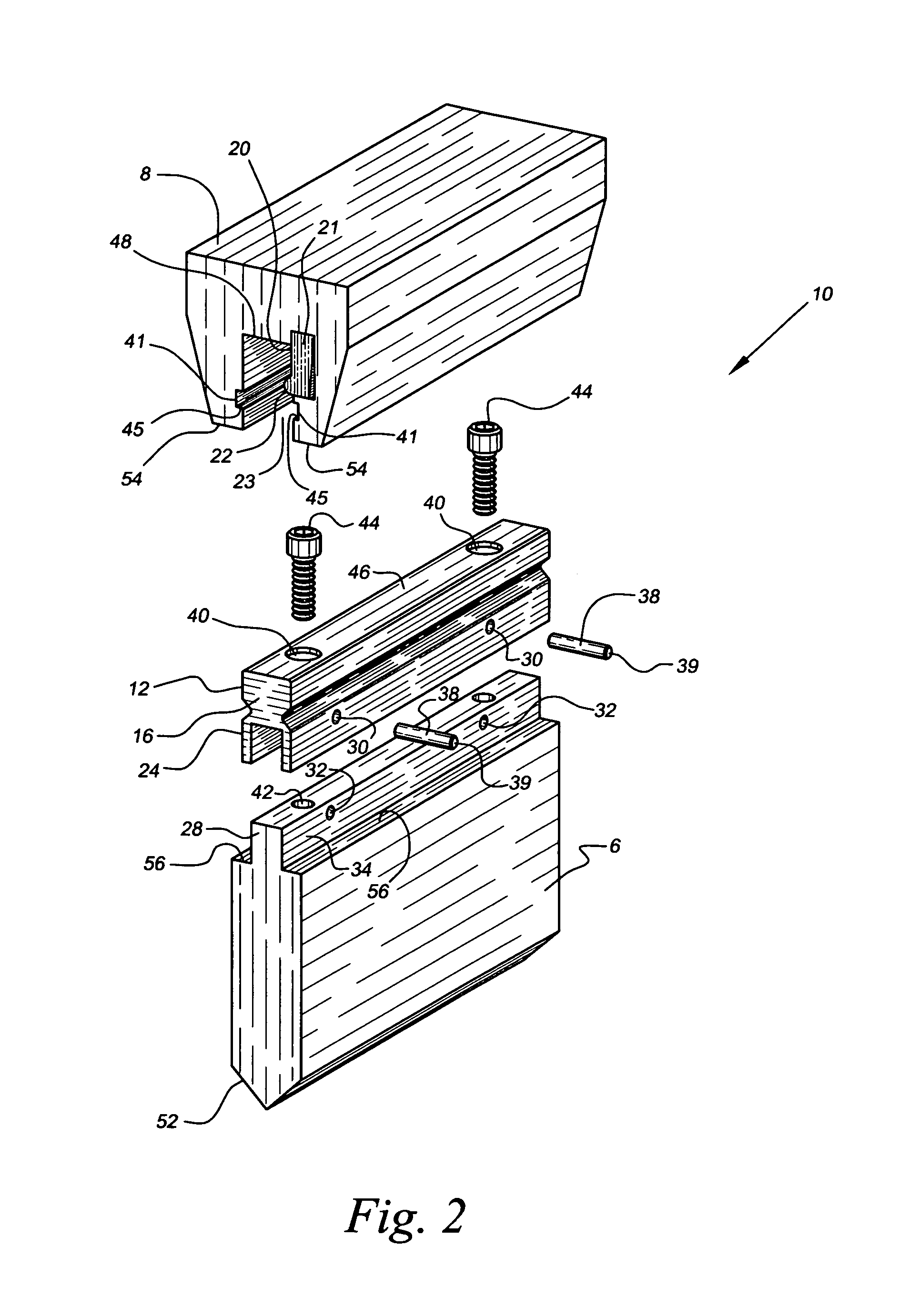
[0026]Referring now to drawings 1–9, a device for securing a typical punch tool 6 to a ram portion 8 of a press brake (not depicted) in accordance with the present invention is denoted as numeral10. The device 10 is a solid piece of cast metal, preferably tool steel, and includes an upper portion 12 having opposing front and back symmetrical outer recesses 14 and 15 extending longitudinally from a first end wall 16 to a second end wall 18, the outer recesses 14 and 15 being configured to snugly receive a corresponding inner wall 20 protuberance 22 of a clamp portion 21 of the ram portion 8 of the press brake. The device 10 snugly inserts, via the first or second end walls 16 and 18, into a cooperating recess 23 in the ram portion 8 such that the device 10, and the punch tool 6 removably attached thereto, are supported by the protuberance 22 of the clamp portion 21 of the ram portion 8 after the press brake grasps and “squeezes” the ram portion 8, thereby urging the protuberance 22 o...


PUM


Abstract

A device (10) for securing a punch tool (6) to a ram portion (8) of a press brake includes an upper portion (12) having opposing front and back outer recesses (14) and (15) extending longitudinally from a first end wall (16) to a second end wall (18), the outer recesses (14) and (15) being configured to snugly receive a corresponding inner wall (20) protuberance (22) of a clamp portion (21) of the ram portion (8) of the press brake as the upper portion (12) is grasped and “squeezed” by the ram portion (8) during operation of the press brake. The device (10) and the punch tool (6) attached thereto, are supported by the protuberance (22). A lower portion (24) of the device (10) includes an inner recess (26) that snugly receives a corresponding upper portion (28) of the punch tool (6). The upper portion (28) of the punch tool (6) is removably secured to the lower portion (24) of the device (10) thereby promoting the quick substitution of punch tools (6) having varying lower portion (52) configurations and identical upper portion (28) configurations.

Description

BACKGROUND OF THE INVENTION[0001]1. Field of the Invention[0002]The present invention relates to press brakes for deforming workpieces into predetermined configurations, and more particularly, to devices and methods that secure a relatively old designed punch tool to a relatively new designed ram portion of a press brake.[0003]2. Background of the Prior Art[0004]Press brake machines and their operative components that are utilized to deform workpieces into predetermined configurations are well known to those of ordinary skill in the art. Typically, a workpiece is disposed between a punch tool and a die, the press brake then forcibly urges the punch tool vertically downward into engagement with the workpiece until the workpiece congruently engages both the punch tool and the die thereby deforming the workpiece into a predetermined configuration consistent with the configurations of the punch tool and the die. An upper end of the punch tool is secured to a ram portion of the press bra...

Claims


Application Information

Patent Timeline
IPC IPC(8): B21D37/04B21J9/02
CPCB21D37/04B21D5/0209
Inventor PELECH, BRUNO J.
Owner PELECH BRUNO J
Why Eureka
Try Eureka