Anti-block catheter

Inactive Publication Date: 2006-05-02
INTEGRA LIFESCI SWITZERLAND SARL
View PDF27 Cites 39 Cited by
  • Summary
  • Abstract
  • Description
  • Claims
  • Application Information

AI Technical Summary

Benefits of technology

[0010]The present invention overcomes the disadvantages that are inherent in prior art fluid management systems by providing an implantable catheter with a coiled end that has a pore or pores, located on the inwardly facing surface of the coil. The fluid management device of the present invention includes a conduit with a proximal portion that is elongate and substantially cylindrical, a distal portion that can assume the shape of a coil with at least one revolution, and a fluid passageway extending between the distal and proximal portions. According to the presen

Problems solved by technology

Blockage of the flow of CSF consequently creates an imbalance between the amount of CSF produced by the choroid plexus and the rate at which CSF is absorbed into the bloodstream, thereby increasing pressure on the brain, which causes the ventricles to enlarge.
The most common complication with shunting is obstruction of the system.
Although obstruction or clogging may occur at any point along the shunt system, it most frequently occurs at the ventricular end of the shunt system.
While there are several ways that the ventricular catheter may become blocked or clogged, obstruction is typically caused by growth of tissue, such as the choroid plexus, around the catheter and into the pores.
The pores of the ventricular catheter can also be obstructed by debris, bacteria, or blood clogged in the pores of the catheter.
Additionally, problems with the ventricular catheter can arise from overdrainage of the CSF, which can cause the ventricle walls to collapse upon the catheter and block the pores in the catheter wall, thereby preventing CSF drainage.
This process can be ineffective, however, due to the small size of the pores of the ventricular catheter and due to the small amount of flushing liquid available in the shunt system.
As with the process of backflushing, using a built-in mecha

Method used


Image

  • Anti-block catheter
  • Anti-block catheter
  • Anti-block catheter

Examples


Example

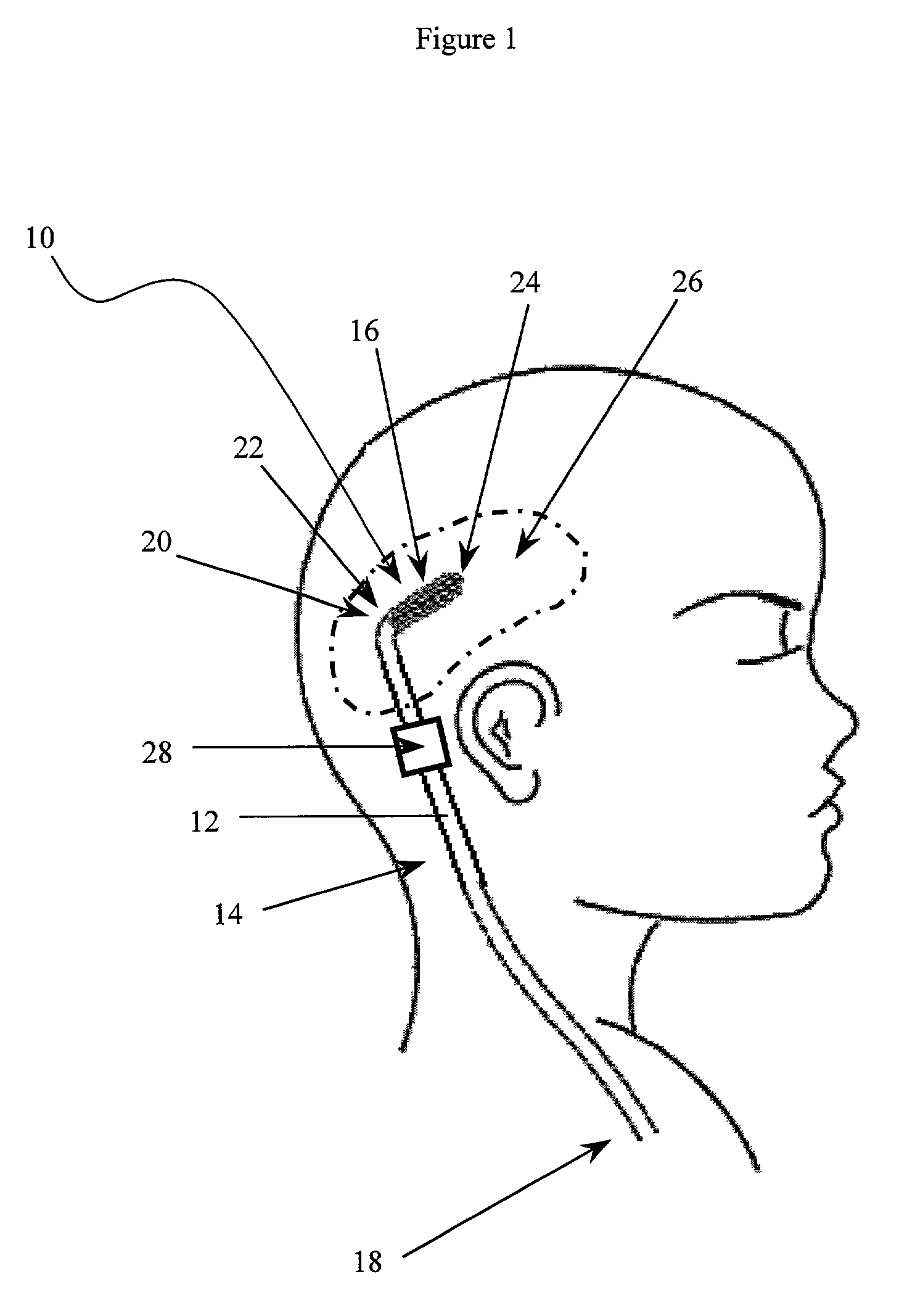
[0020]The implantable fluid management device of the present invention facilitates the removal or introduction of fluid to a treatment site. By way of example, a distal portion of the device can be implanted in the ventricle of the brain to drain excess fluid from within the ventricles, directing it to another site in the patient's body. The fluid management device of the present invention is advantageous as its construction enables fluid to be drained while minimizing the risk that the drainage catheter will be blocked or occluded.

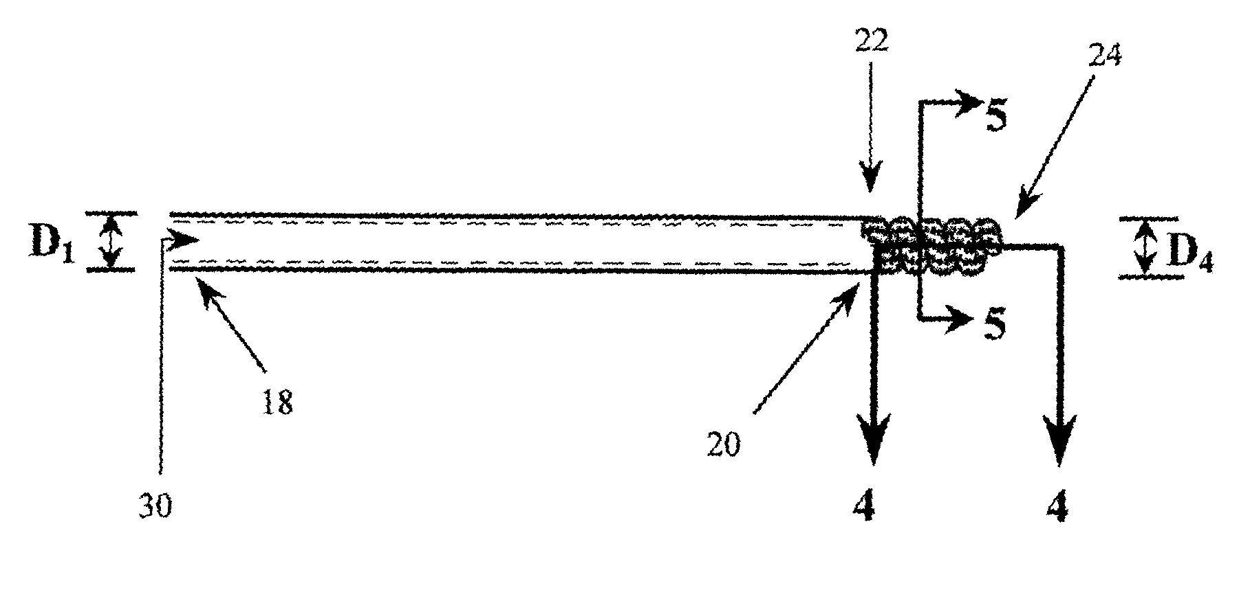
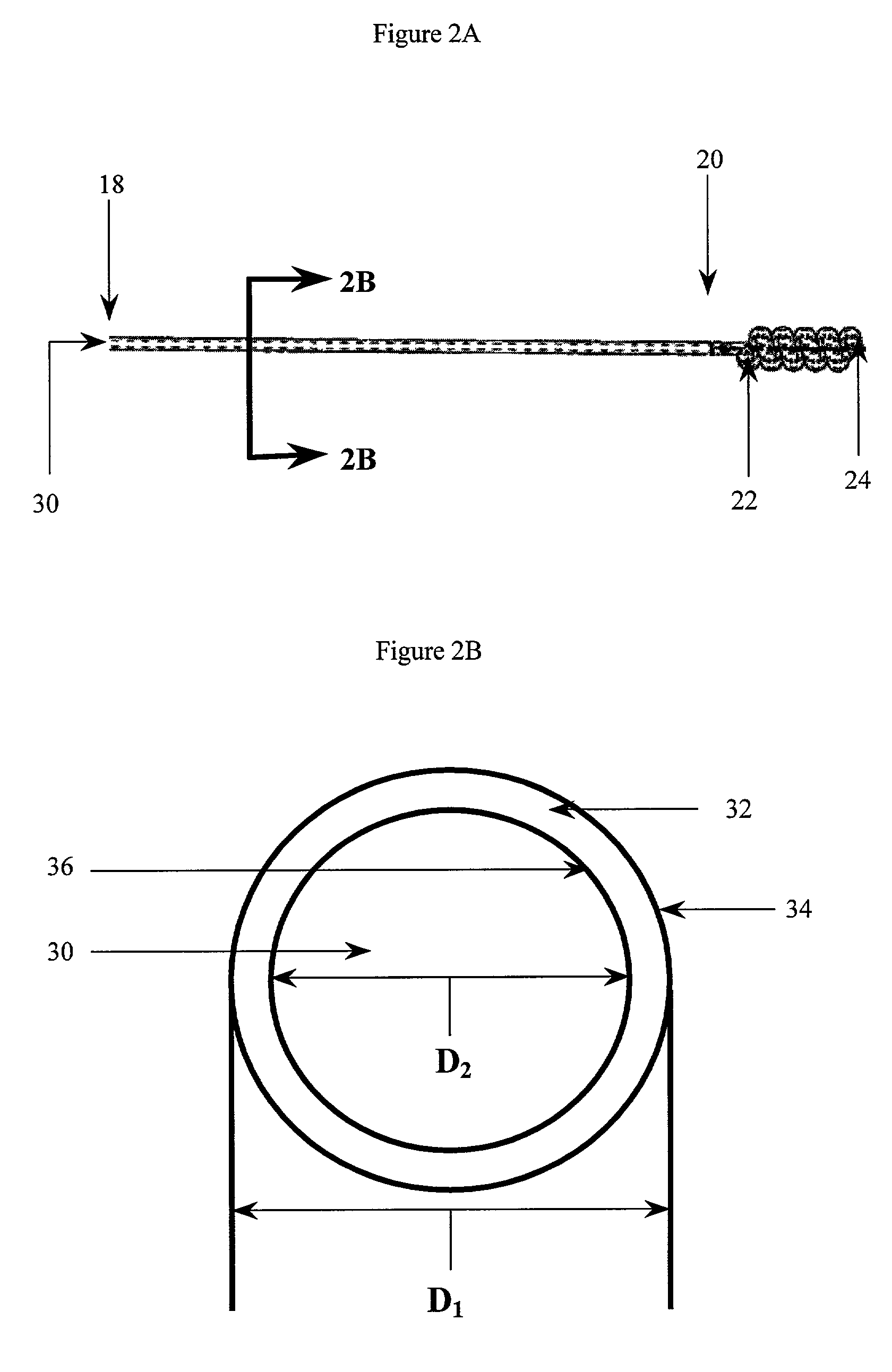
[0021]As shown in FIG. 1, the implantable fluid management device 10 includes a catheter 12 having proximal and distal portions 14, 16 with a fluid passageway extending therebetween. The proximal portion 14 of the catheter 12 has a first, open end 18 and a transition end 20 and a lumen 30 (FIGS. 2A, 3A and 3B) connecting the two ends. The distal portion 16 of the catheter 12 is defined by an outer wall 44 (FIGS. 4 and 5) and has a first, connecting end 22...


PUM


Abstract

An implantable fluid management device includes a catheter with an elongate proximal portion, a flexible distal portion, and a fluid passageway flowing therethrough. The distal portion includes a coil-shaped portion that defines a spiral having at least one turn. The distal portion of the catheter includes at least one pore in fluid communication with the fluid passageway of the catheter, which is located on an internal portion of the spiral. The positioning of the pore(s) on the internal portion of the spiral protects the pore(s) from obstruction or occlusion caused by tissue growing into or around the catheter.

Description

FIELD OF THE INVENTION[0001]The present invention relates generally to a fluid management device that minimizes the risk of blockage or obstruction of the catheter pores, and more particularly, to a fluid management device with a catheter that includes a coiled portion having pores on the internal surface of the coil.BACKGROUND OF THE INVENTION[0002]Hydrocephalus is a neurological condition that is caused by the abnormal accumulation of cerebrospinal fluid (CSF) within the ventricles, or cavities, of the brain. CSF is a clear, colorless fluid that is primarily produced by the choroid plexus and surrounds the brain and spinal cord. CSF constantly circulates through the ventricular system of the brain and is ultimately absorbed into the bloodstream. CSF aids in the protection of the brain and spinal cord. Because CSF keeps the brain and spinal cord buoyant, it acts as a protective cushion or “shock absorber” to prevent injuries to the central nervous system.[0003]Hydrocephalus, which ...

Claims


Application Information

Patent Timeline
IPC IPC(8): A61M5/00A61M25/00A61M27/00
CPCA61M27/006A61M25/0021A61M25/0041A61M2025/0057A61M25/008A61M25/0068
Inventor ROSENBERG, MEIROSTIGUY, PIERRE
Owner INTEGRA LIFESCI SWITZERLAND SARL
Why Eureka
Try Eureka